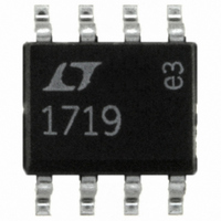
LT1719CS8#PBF Linear Technology, LT1719CS8#PBF Datasheet - Page 13

LT1719CS8#PBF
Manufacturer Part Number
LT1719CS8#PBF
Description
IC COMP R-R I/O SGL 3/5V 8-SOIC
Manufacturer
Linear Technology
Series
UltraFast™r
Type
General Purposer
Specifications of LT1719CS8#PBF
Number Of Elements
1
Output Type
CMOS, Rail-to-Rail, TTL
Voltage - Supply
2.7 V ~ 10.5 V
Mounting Type
Surface Mount
Package / Case
8-SOIC (0.154", 3.90mm Width)
Comparator Type
General Purpose
No. Of Comparators
1
Response Time
4.5ns
Ic Output Type
CMOS, TTL
Output Compatibility
CMOS, TTL
Supply Current
4.2mA
Supply Voltage Range
2.7V To 10.5V
Rohs Compliant
Yes
Lead Free Status / RoHS Status
Lead free / RoHS Compliant
Available stocks
Company
Part Number
Manufacturer
Quantity
Price
APPLICATIONS
Figure 6a shows the standard TTL to Positive ECL (PECL)
resistive level translator. This translator cannot be used for
the LT1719, or with CMOS logic, because it depends on the
820 resistor to limit the output swing (V
TTL gate with its so-called totem-pole output. The LT1719
is fabricated in a complementary bipolar process and the
output stage has a PNP driver that pulls the output nearly
all the way to the supply rail, even when sourcing 10mA.
Figure 6b shows a three resistor level translator for inter-
facing the LT1719 to ECL running off the same supply rail.
No pull-down on the output of the LT1719 is needed, but
pull-down R3 limits the V
needed because ECL inputs have both a minimum and
maximum V
values are given for both ECL interface types; in both cases
it is assumed that the LT1719 operates from the same
supply rail.
Figure 6c shows the case of translating to PECL from an
LT1719 powered by a 3V supply rail. Again, resistor values
are given for both ECL interface types. This time four re-
sistors are needed, although with 10KH/E, R3 is not needed.
In that case, the circuit resembles the standard TTL trans-
lator of Figure 6a, but the function of the new resistor, R4,
is much different. R4 loads the LT1719 output when high
so that the current flowing through R1 doesn’t forward
bias the LT1719’s internal ESD clamp diode. Although this
diode can handle 20mA without damage, normal opera-
tion and performance of the output stage can be impaired
above 100 A of forward current. R4 prevents this with the
minimum additional power dissipation.
Finally, Figure 6d shows the case of driving standard,
negative-rail, ECL with the LT1719. Resistor values are
given for both ECL interface types and for both a 5V and 3V
LT1719 supply rail. Again, a fourth resistor, R4 is needed
to prevent the low state current from flowing out of the
LT1719, turning on the internal ESD/substrate diodes.
Resistor R4 again prevents this with the minimum addi-
tional power dissipation.
IH
specification for proper operation. Resistor
U
INFORMATION
IH
U
seen by the PECL gate. This is
W
OH
) of the all-NPN
U
Of course, in the SO-8 package, if the V
the same as the ECL negative supply, the GND pin can be
tied to it as well and + V
has the same power rails as the ECL and the circuits of
Figure 6b can be used.
For all the dividers shown, the output impedance is about
110 . This makes these fast, less than a nanosecond, with
most layouts. Avoid the temptation to use speedup capaci-
tors. Not only can they foul up the operation of the ECL gate
because of overshoots, they can damage the ECL inputs,
particularly during power-up of separate supply
configurations.
Similar circuits can be used with the emerging LVECL and
LVPECL standards.
The level translator designs shown assume one gate load.
Multiple gates can have significant I
transmission line routing and termination issues also
make this case difficult.
ECL, and particularly PECL, is valuable technology for high
speed system design, but it must be used with care. With
less than a volt of swing, the noise margins need to be
evaluated carefully. Note that there is some degradation of
noise margin due to the 5% resistor selections shown.
With 10KH/E, there is no temperature compensation of the
logic levels, whereas the LT1719 and the circuits shown
give levels that are stable with temperature. This will lower
the noise margin over temperature. In some configura-
tions it is possible to add compensation with diode or
transistor junctions in series with the resistors of these
networks.
For more information on ECL design, refer to the ECLiPS
data book (DL140), the 10KH system design handbook
(HB205) and PECL design (AN1406), all from Motorola,
now ON semiconductor.
S
grounded. Then the output stage
IH
EE
loading, and the
of the LT1719 is
LT1719
13


