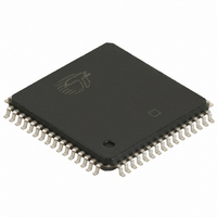
CY7C4275-15ASC Cypress Semiconductor Corp, CY7C4275-15ASC Datasheet - Page 2

CY7C4275-15ASC
Manufacturer Part Number
CY7C4275-15ASC
Description
IC DEEP SYN FIFO 32KX18 64-STQFP
Manufacturer
Cypress Semiconductor Corp
Series
CY7Cr
Datasheet
1.CY7C4275-15ASC.pdf
(20 pages)
Specifications of CY7C4275-15ASC
Function
Synchronous
Memory Size
576K (32K x 18)
Data Rate
100MHz
Access Time
10ns
Voltage - Supply
3.3V
Operating Temperature
-40°C ~ 85°C
Mounting Type
Surface Mount
Package / Case
64-LQFP
Configuration
Dual
Density
576Kb
Access Time (max)
10ns
Word Size
18b
Organization
32Kx18
Sync/async
Synchronous
Expandable
Yes
Bus Direction
Uni-Directional
Package Type
TQFP
Clock Freq (max)
66.7MHz
Operating Supply Voltage (typ)
5V
Operating Supply Voltage (min)
4.5V
Operating Supply Voltage (max)
5.5V
Supply Current
50mA
Operating Temp Range
0C to 70C
Operating Temperature Classification
Commercial
Mounting
Surface Mount
Pin Count
64
Lead Free Status / RoHS Status
Contains lead / RoHS non-compliant
Available stocks
Company
Part Number
Manufacturer
Quantity
Price
Company:
Part Number:
CY7C4275-15ASC
Manufacturer:
Cypress Semiconductor Corp
Quantity:
10 000
Pin Configurations
Functional Description
The CY7C4275/85 provides five status pins. These pins are decod-
ed to determine one of five states: Empty, Almost Empty, Half Full,
Almost Full, and Full (see Table 2). The Half Full flag shares the
WXO pin. This flag is valid in the stand-alone and width-expansion
configurations. In the depth expansion, this pin provides
the expansion out (WXO) information that is used to signal
the next FIFO when it will be activated.
Selection Guide
Document #: 38-06008 Rev. *B
GND
V
Maximum Frequency (MHz)
Maximum Access Time (ns)
Minimum Cycle Time (ns)
Minimum Data or Enable Set-Up (ns)
Minimum Data or Enable Hold (ns)
Maximum Flag Delay (ns)
Active Power Supply
Current (I
Density
Packages
D
D
D
D
D
D
D
D
CC
D
D
D
D
D
D
D
14
13
12
11
10
9
8
7
6
5
4
3
2
1
0
10
11
12
13
14
15
16
17
18
19
20
21
22
23
24
25
26
2728 2930
9 8 7
CC1
) (mA)
6
3132 33 34 35 36 37 38 3940 4142 43
5
CY7C4275
CY7C4285
4
3 2 1 68
Top View
PLCC
64-pin 10x10 TQFP,
(continued)
68-pin PLCC
67
CY7C4275
32K x 18
66 65 64 63 62 61
Commercial
Industrial
60
59
58
57
56
55
54
53
52
51
50
49
48
47
46
45
44
64-pin 10x10 TQFP,
V
Q
Q
GND
Q
Q
V
Q
Q
GND
Q
Q
V
Q
Q
GND
Q
4275–2
CC
CC
CC
14
13
12
11
10
9
8
7
6
5
4
68-pin PLCC
CY7C4285
/SMODE
64K x 18
7C4275/85-10
100
D
D
D
D
D
D
0.5
10
50
55
D
D
D
D
D
D
D
D
D
D
8
3
8
15
14
13
12
11
10
9
8
7
6
5
4
3
2
1
0
The Empty and Full flags are synchronous, i.e., they change
state relative to either the read clock (RCLK) or the write clock
(WCLK). When entering or exiting the Empty states, the flag is
updated exclusively by the RCLK. The flag denoting Full states
is updated exclusively by WCLK. The synchronous flag archi-
tecture guarantees that the flags will remain valid from one
clock cycle to the next. The Almost Empty/Almost Full flags
become synchronous if the V
configurations are fabricated using an advanced 0.5μ
CMOS technology. Input ESD protection is greater than
2001V, and latch-up is prevented by the use of guard rings.
1
2
3
4
5
6
7
8
9
10
11
12
13
14
15
16
7C4275/85-15
CY7C4275
CY7C4285
66.7
Top View
10
15
10
50
TQFP
4
1
CC
/SMODE is tied to V
7C4275/85-25
48
47
46
45
44
43
42
41
40
39
38
37
36
35
34
33
CY7C4275
CY7C4285
40
15
25
15
50
6
1
Page 2 of 20
4275–3
Q
Q
GND
Q
Q
V
Q
Q
GND
Q
Q
Q
Q
GND
Q
V
CC
CC
14
13
12
11
10
9
8
7
6
5
4
SS
. All
[+] Feedback


