SY89841UMG Micrel Inc, SY89841UMG Datasheet - Page 7
SY89841UMG
Manufacturer Part Number
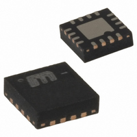
SY89841UMG
Description
IC MUX 2:1 LVDS RPE 16-MLF
Manufacturer
Micrel Inc
Type
Multiplexerr
Series
SY89r
Datasheet
1.SY89841UMG.pdf
(15 pages)
Specifications of SY89841UMG
Circuit
1 x 2:1
Independent Circuits
1
Voltage Supply Source
Single Supply
Voltage - Supply
3 V ~ 3.6 V
Operating Temperature
-40°C ~ 85°C
Mounting Type
Surface Mount
Package / Case
16-MLF®, QFN
Number Of Clock Inputs
2
Mode Of Operation
Differential
Output Logic Level
LVDS
Operating Supply Voltage (min)
2.375V
Operating Supply Voltage (typ)
2.5V
Operating Supply Voltage (max)
2.625V
Package Type
MLF
Operating Temp Range
-40C to 85C
Operating Temperature Classification
Industrial
Signal Type
CML/LVDS/PECL
Mounting
Surface Mount
Pin Count
16
Lead Free Status / RoHS Status
Lead free / RoHS Compliant
Current - Output High, Low
-
Lead Free Status / RoHS Status
Compliant, Lead free / RoHS Compliant
Other names
576-2095-5
SY89841UMG
SY89841UMG
Available stocks
Company
Part Number
Manufacturer
Quantity
Price
Company:

Part Number:
SY89841UMG
Manufacturer:
MICREL
Quantity:
39


Micrel, Inc.
AC Electrical Characteristics
V
Notes:
8. High-frequency AC-parameters are guaranteed by design and characterization.
9. Propagation delay is measured with input t
10. Part-to-part skew is defined for two parts with identical power supply voltages at the same temperature and with no skew of the edges at
11. Random Jitter is measured with a K28.7 character pattern, measured at <f
12. Cycle-to-cycle jitter definition: the variation of periods between adjacent cycles, T
13. Total Jitter definition: with an ideal clock input of frequency <f
14. Crosstalk is measured at the output while applying two similar differential clock frequencies that are asynchronous with respect to each
February 2005
Symbol
f
t
t
Tempco
t
t
t
CC
MAX
pd
pd
SKEW
Jitter
r,
the respective inputs.
output signal.
than the specified peak-to-peak jitter value.
other at the inputs.
t
f
= 2.5V ±5%; R
Parameter
Maximum Operating Frequency
Differential Propagation Delay
In-to-Q
In-to-Q
SEL-to-Q
SEL-to-Q
Differential Propagation Delay
Temperature Coefficient
Part-to-Part Skew
Random Jitter
Cycle-to-Cycle Jitter
Total Jitter (TJ)
Crosstalk-Induced Jitter
Output Rise/Fall Time (20% to 80%)
L
= 100 across output pair or equivalent; T
r
, t
f
(8)
300ps (20% to 80%) and V
Condition
Clock
V
V
RPE enabled, see Timing Diagram
RPE disabled (V
Note 10
Note 11
Note 12
Note 13
Note 14
At full output swing.
IN
IN
MAX
= 100mV to 200mV
= 200mV to 800mV
, no more than one output edge in 10
7
A
MAX
IL
= –40°C to + 85°C, unless otherwise stated.
.
IN
800mV.
= V
n
– T
CC
(9)
(9)
/2)
n-1
where T is the time between rising edges of the
hbwhelp@micrel.com
12
output edges will deviate by more
Min
470
440
550
1.5
30
Typ
625
575
115
2.0
70
or (408) 955-1690
M9999-021405
Max
870
800
900
200
150
0.7
17
10
1
1
SY89841U
cycles
Units
ps
ps
ps
GHz
fs/
ps
ps
ps
ps
ps
ps
(rms)
(rms)
(rms)
o
(pp)
C
Related parts for SY89841UMG
Image
Part Number
Description
Manufacturer
Datasheet
Request
R

Part Number:
Description:
3.3V 800MHz Ultrasmall Dual LVTTL-to-LVPECL Translator (I Temp, Green)
Manufacturer:
Micrel Inc
Datasheet:

Part Number:
Description:
IC XPOINT SW 4X4 PREC 44-MLF
Manufacturer:
Micrel Inc
Datasheet:
Part Number:
Description:
IC XPOINT SWITCH 3.2GBPS 44-MLF
Manufacturer:
Micrel Inc
Datasheet:
Part Number:
Description:
IC XPOINT SWITCH 3.2GBPS 44-MLF
Manufacturer:
Micrel Inc
Datasheet:
Part Number:
Description:
IC XPOINT SWITCH 4X4 LVDS 44-MLF
Manufacturer:
Micrel Inc
Datasheet:
Part Number:
Description:
IC XPOINT SWITCH 4X4 LVDS 44-MLF
Manufacturer:
Micrel Inc
Datasheet:

Part Number:
Description:
IC MUX 2:1 LVPECL DIFF 16MLF
Manufacturer:
Micrel Inc
Datasheet:
Part Number:
Description:
IC MUX 2:1 LVPECL RPE/FSI 16MLF
Manufacturer:
Micrel Inc
Datasheet:
Part Number:
Description:
IC MUX 2:1 LVDS RPE 16-MLF
Manufacturer:
Micrel Inc
Datasheet:
Part Number:
Description:
IC MUX 8:1 PREC LP 44-MLF
Manufacturer:
Micrel Inc
Datasheet:

Part Number:
Description:
IC MUX 2:1 LVDC DUAL 3.3V 32MLF
Manufacturer:
Micrel Inc
Datasheet:
Part Number:
Description:
IC MUX 4:1 LVDS DIFF 2.5V 32MLF
Manufacturer:
Micrel Inc
Datasheet:
Part Number:
Description:
IC MUX 4:1 LVDS DIFF 3.3V 32MLF
Manufacturer:
Micrel Inc
Datasheet:
Part Number:
Description:
IC MUX 4:1 LVDS DIFF 2.5V 32MLF
Manufacturer:
Micrel Inc
Datasheet:
Part Number:
Description:
IC MUX 4:1 LVDS DIFF 3.3V 32MLF
Manufacturer:
Micrel Inc
Datasheet: