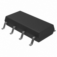
S-93C66BR0I-J8T1G Seiko Instruments, S-93C66BR0I-J8T1G Datasheet - Page 21

S-93C66BR0I-J8T1G
Manufacturer Part Number
S-93C66BR0I-J8T1G
Description
IC EEPROM 4KBIT 500KHZ 8SOP
Manufacturer
Seiko Instruments
Datasheet
1.S-93C46BD0I-T8T1G.pdf
(50 pages)
Specifications of S-93C66BR0I-J8T1G
Format - Memory
EEPROMs - Serial
Memory Type
EEPROM
Memory Size
4K (256 x 16)
Speed
500kHz
Interface
3-Wire Serial
Voltage - Supply
1.8 V ~ 5.5 V
Operating Temperature
-40°C ~ 85°C
Package / Case
8-SOP
Lead Free Status / RoHS Status
Lead free / RoHS Compliant
Rev.7.0
3-Wire Interface (Direct Connection between DI and DO)
I/O Pin
1. Connection of input pins
2. Equivalent circuit of input and output pin
There are two types of serial interface configurations: a 4-wire interface configured using the CS, SK, DI, and DO
pins, and a 3-wire interface that connects the DI input pin and DO output pin.
When the 3-wire interface is employed, a period in which the data output from the CPU and the data output from the
serial memory collide may occur, causing a malfunction. To prevent such a malfunction, connect the DI and DO
pins of the S-93C46B/56B/66B via a resistor (10 to 100 k
in being input to the DI pin (refer to “ Figure 23 Connection of 3-Wire Interface ”).
All the input pins of the S-93C46B/56B/66B employ a CMOS structure, so design the equipment so that high
impedance will not be input while the S-93C46B/56B/66B is operating. Especially, deselect the CS input (a low
level) when turning on/off power and during standby. When the CS pin is deselected (a low level), incorrect
data writing will not occur. Connect the CS pin to GND via a resistor (10 to 100 k
prevent malfunction, it is recommended to use equivalent pull-down resistors for pins other than the CS pin.
The following shows the equivalent circuits of input pins of the S-93C46B/56B/66B. None of the input pins
incorporate pull-up and pull-down elements, so special care must be taken when designing to prevent a floating
status.
Output pins are high-level/low-level/high-impedance tri-state outputs. The TEST pin is disconnected from the
internal circuit by a switching transistor during normal operation. As long as the absolute maximum rating is
satisfied, the TEST pin and internal circuit will never be connected.
_00
Figure 23 Connection of 3-Wire Interface
CPU
SIO
Seiko Instruments Inc.
R : 10 to 100 kΩ
Ω
) so that the data output from the CPU takes precedence
S-93C46B/56B/66B
DI
DO
3-WIRE SERIAL E
S-93C46B/56B/66B
Ω
pull-down resistor). To
2
PROM
21


