DS1216D Maxim Integrated Products, DS1216D Datasheet - Page 6
DS1216D
Manufacturer Part Number
DS1216D
Description
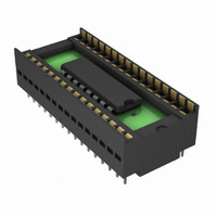
IC SMART/RAM 5V 256K/1M 32-DIP
Manufacturer
Maxim Integrated Products
Datasheet
1.DS1216C.pdf
(14 pages)
Specifications of DS1216D
Controller Type
Smartwatch RAM
Voltage - Supply
4.5 V ~ 5.5 V
Operating Temperature
0°C ~ 70°C
Package / Case
32-DIP (0.600", 15.24mm) Socket
Lead Free Status / RoHS Status
Contains lead / RoHS non-compliant
Available stocks
Company
Part Number
Manufacturer
Quantity
Price
Company:

Part Number:
DS1216D
Manufacturer:
DALLAS
Quantity:
5 530
Company:
Part Number:
DS1216D
Manufacturer:
DALLAS
Quantity:
5 510
Part Number:
DS1216D
Manufacturer:
MXX
Quantity:
20 000


SMARTWATCH REGISTER INFORMATION
The SmartWatch information is contained in eight registers of 8 bits, each of which is sequentially
accessed
updating
individual bits within a register could produce erroneous results. These read/write registers are defined in
Figure 3.
Data contained in the SmartWatc regi ters is in binary-coded decimal (BCD) format. Reading and
writing the registers is always accomplished by stepping through all eight registers, starting with bit 0 of
register 0 and ending with bit 7 of register 7.
AM-PM/12-/24-MODE
Bit 7 of th
mode is se
mode, bit 5 is the second 10-hour bit (20 to 23 hours).
OSCILLATOR AND RESET BITS
Bits 4 and 5 of the day register are used to control the RST and oscillator functions.
RST (pin 1). When the RST bit is set to logic 1, the RST input pin is ignored. When th
logic 0, a low input on the RST pin will cause the SmartWatch to abort data transfe
data in the watch registers. Bit 5 controls the oscillator. When set to logic 1, the oscilla
to logic 0, the oscillator turns on and the watch becomes operational. These bits are
factory set to logic 1.
ZERO BITS
Registers 1 to 6 contain one or more bits that always read logic 0. When writing these
or 0 is acceptable.
ADDITIONAL INFORMATION
Refer to Application Note 52: Using the Dallas Phantom Real-Time Clocks (available on our website at
www.maxim-ic.com/RTCapps
phantom clock contained within the SmartWatch.
one b
the S
e hours register is defined as the 12-hour or 24-hour mod
lected. In the 12-hour mode, bit 5 is the A
mar
it a a me after the 64-bit p ttern
tW
t
atch registers, eac must be handled in g ups of 8 bits. Writing and reading
ti
) for information about using regarding optional modifications and the
h
h
s
a
6 of 14
M/PM bit with logic high being PM. In the 24-hour
re
cog ition sequence has been completed. When
n
DS1216 SmartWatch RAM/SmartWatch ROM
ro
e-select bit. When high, the 12-hour
r without changing
tor is off. When set
locations, a logic 1
Bit 4 controls the
e RST bit is set to
shipped from the
Related parts for DS1216D
Image
Part Number
Description
Manufacturer
Datasheet
Request
R

Part Number:
Description:
MAX7528KCWPMaxim Integrated Products [CMOS Dual 8-Bit Buffered Multiplying DACs]
Manufacturer:
Maxim Integrated Products
Datasheet:
Part Number:
Description:
Single +5V, fully integrated, 1.25Gbps laser diode driver.
Manufacturer:
Maxim Integrated Products
Datasheet:
Part Number:
Description:
Single +5V, fully integrated, 155Mbps laser diode driver.
Manufacturer:
Maxim Integrated Products
Datasheet:
Part Number:
Description:
VRD11/VRD10, K8 Rev F 2/3/4-Phase PWM Controllers with Integrated Dual MOSFET Drivers
Manufacturer:
Maxim Integrated Products
Datasheet:
Part Number:
Description:
Highly Integrated Level 2 SMBus Battery Chargers
Manufacturer:
Maxim Integrated Products
Datasheet:
Part Number:
Description:
Current Monitor and Accumulator with Integrated Sense Resistor; ; Temperature Range: -40°C to +85°C
Manufacturer:
Maxim Integrated Products
Part Number:
Description:
TSSOP 14/A�/RS-485 Transceivers with Integrated 100O/120O Termination Resis
Manufacturer:
Maxim Integrated Products
Part Number:
Description:
TSSOP 14/A�/RS-485 Transceivers with Integrated 100O/120O Termination Resis
Manufacturer:
Maxim Integrated Products
Part Number:
Description:
QFN 16/A�/AC-DC and DC-DC Peak-Current-Mode Converters with Integrated Step
Manufacturer:
Maxim Integrated Products
Part Number:
Description:
TDFN/A/65V, 1A, 600KHZ, SYNCHRONOUS STEP-DOWN REGULATOR WITH INTEGRATED SWI
Manufacturer:
Maxim Integrated Products
Part Number:
Description:
Integrated Temperature Controller f
Manufacturer:
Maxim Integrated Products
Part Number:
Description:
SOT23-6/I�/45MHz to 650MHz, Integrated IF VCOs with Differential Output
Manufacturer:
Maxim Integrated Products
Part Number:
Description:
SOT23-6/I�/45MHz to 650MHz, Integrated IF VCOs with Differential Output
Manufacturer:
Maxim Integrated Products
Part Number:
Description:
EVALUATION KIT/2.4GHZ TO 2.5GHZ 802.11G/B RF TRANSCEIVER WITH INTEGRATED PA
Manufacturer:
Maxim Integrated Products
Part Number:
Description:
QFN/E/DUAL PCIE/SATA HIGH SPEED SWITCH WITH INTEGRATED BIAS RESISTOR
Manufacturer:
Maxim Integrated Products
Datasheet: