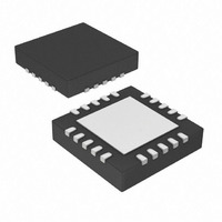
MCP73871-2CAI/ML Microchip Technology, MCP73871-2CAI/ML Datasheet - Page 26

MCP73871-2CAI/ML
Manufacturer Part Number
MCP73871-2CAI/ML
Description
IC USB/AC BATT CHRGR W/PPM 20QFN
Manufacturer
Microchip Technology
Specifications of MCP73871-2CAI/ML
Battery Type
Lithium-Ion (Li-Ion), Lithium-Polymer (Li-Pol)
Function
Charge Management
Voltage - Supply
4.4 V ~ 6 V
Operating Temperature
-40°C ~ 85°C
Mounting Type
Surface Mount
Package / Case
20-VFQFN Exposed Pad
Input Voltage
6V
Battery Charge Voltage
4.5V
Charge Current Max
1A
Battery Ic Case Style
QFN
No. Of Pins
20
No. Of Series Cells
1
Product
Charge Management
Output Voltage
4.2 V
Output Current
50 mA to 1000 mA
Operating Supply Voltage
4.5 V to 6 V
Maximum Operating Temperature
+ 85 C
Minimum Operating Temperature
- 40 C
Mounting Style
SMD/SMT
Lead Free Status / RoHS Status
Lead free / RoHS Compliant
For Use With
MCP73871DM-VPCC - DEMO BOARD FOR MCP73871MCP73871EV - EVALUATION BOARD FOR MCP73871
Lead Free Status / Rohs Status
Lead free / RoHS Compliant
Available stocks
Company
Part Number
Manufacturer
Quantity
Price
Company:
Part Number:
MCP73871-2CAI/ML
Manufacturer:
MICROCHIP
Quantity:
12 000
Part Number:
MCP73871-2CAI/ML
Manufacturer:
MICROCHIP/微芯
Quantity:
20 000
MCP73871
6.1
Due to the low efficiency of linear charging, the most
important factors are thermal design and cost, which
are a direct function of the input voltage, output current
and thermal impedance between the battery charger
and the ambient cooling air. The worst-case situation is
when
Preconditioning mode to the Constant Current mode. In
this situation, the battery charger has to dissipate the
maximum power. A trade-off must be made between
the charge current, cost and thermal requirements of
the charger.
6.1.1
Selection of the external components in
crucial to the integrity and reliability of the charging
system. The following discussion is intended as a guide
for the component selection process.
6.1.1.1
The preferred fast charge current for Lithium-Ion cells
should always follow references and guidances from
battery manufacturers. For example, a 1000 mAh
battery pack has a preferred fast charge current of
0.7C. Charging at 700 mA provides the shortest charge
cycle times without degradation to the battery pack
performance or life.
6.1.1.2
The worst-case power dissipation in the battery
charger occurs when the input voltage is at the
maximum and the device has transitioned from the
Preconditioning mode to the Constant-current mode. In
this case, the power dissipation is:
EQUATION 6-1:
For example, power dissipation with a 5V, ±10% input
voltage source and 500 mA, ±10% fast charge current
is:
EXAMPLE 6-1:
DS22090B-page 26
Where:
PowerDissipation
I
V
PowerDissipation
V
REGMAX
PTHMIN
DDMAX
the
Application Circuit Design
COMPONENT SELECTION
Charge Current
Thermal Considerations
device
= the maximum input voltage
= the maximum fast charge current
= the minimum transition threshold
voltage
=
=
(
V
DDMAX
(
has
5.5V 2.7V
–
transitioned
–
V
PTHMIN
)
×
550
)
mA
×
Figure 6-1
I
REGMAX
from
=
1.54W
the
is
This power dissipation with the battery charger in the
QFN-20 package will cause thermal regulation to be
entered as depicted. Alternatively, the 4 mm x 4 mm
DFN package could be utilized to reduce heat by
adding vias on the exposed pad.
6.1.1.3
The MCP73871 device is stable with or without a
battery load. In order to maintain good AC stability in
the Constant Voltage mode, a minimum capacitance of
4.7 µF is recommended to bypass the V
This capacitance provides compensation when there is
no battery load. In addition, the battery and
interconnections appear inductive at high frequencies.
These elements are in the control feedback loop during
Constant Voltage mode. Therefore, the bypass
capacitance may be necessary to compensate for the
inductive nature of the battery pack.
Virtually any good quality output filter capacitor can be
used, independent of the capacitor’s minimum
Effective Series Resistance (ESR) value. The actual
value of the capacitor (and its associated ESR)
depends on the output load current. A 4.7 µF ceramic,
tantalum or aluminum electrolytic capacitor at the
output is usually sufficient to ensure stability for charge
currents up to a 1000 mA.
6.1.1.4
The MCP73871 device provides protection from a
faulted or shorted input. Without the protection, a
faulted or shorted input would discharge the battery
pack through the body diode of the internal pass
transistor.
6.1.1.5
The charge temperature window can be set by placing
fixed value resistors in series-parallel with a thermistor.
The resistance values of R
with the following equations in order to set the
temperature window of interest.
For NTC thermistors:
EQUATION 6-2:
Where:
R
R
COLD
R
R
HOT
T1
T2
24k
External Capacitors
Reverse-Blocking Protection
Temperature Monitoring
=
=
=
=
5k
Ω
Ω
=
=
the fixed series resistance
the fixed parallel resistance
the thermistor resistance at the
lower temperature of interest
the thermistor resistance at the
upper temperature of interest
R
R
T1
T1
© 2009 Microchip Technology Inc.
T1
+
+
R
-------------------------------- -
R
R
---------------------------- -
R
and R
T2
T2
T2
T2
×
+
×
+
R
R
R
R
T2
COLD
COLD
HOT
HOT
can be calculated
BAT
pin to V
SS
.


