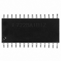
ICM7228AIBIZ Intersil, ICM7228AIBIZ Datasheet - Page 8

ICM7228AIBIZ
Manufacturer Part Number
ICM7228AIBIZ
Description
IC DRIVER DECODER 8DGT CA 28SOIC
Manufacturer
Intersil
Datasheet
1.ICM7228AIBIZ.pdf
(18 pages)
Specifications of ICM7228AIBIZ
Display Type
LED
Configuration
7 Segment
Digits Or Characters
8 Digits
Current - Supply
200µA
Voltage - Supply
4 V ~ 6 V
Operating Temperature
-40°C ~ 85°C
Mounting Type
Surface Mount
Package / Case
28-SOIC (7.5mm Width)
Lead Free Status / RoHS Status
Lead free / RoHS Compliant
Interface
-
Available stocks
Company
Part Number
Manufacturer
Quantity
Price
Company:
Part Number:
ICM7228AIBIZ
Manufacturer:
Intersil
Quantity:
500
PIN NO.
PIN NO.
10
11
12
13
14
15
16
17
18
19
20
21
22
23
24
25
26
27
28
9
1
2
3
4
5
6
7
MODE
ID4,
(SHUTDOWN)
ID1
ID0
ID2
ID3
DIGIT 1
DlGlT 2
DIGIT 5
DlGlT 8
V
DIGIT 4
DlGlT 7
DlGlT 6
DIGlT 3
SEG f
SEG d
SEG g
SEG a
DIGIT 4
DlGlT 6
DIGIT 3
DlGlT 1
ID6,
(HEXA/CODE B)
ID5, (DECODE)
ID7,
(DATA COMING)
V
DD
SS
NAME
NAME
TABLE 1. ICM7228A PIN ASSIGNMENTS AND DESCRIPTIONS (Continued)
8
FUNCTION
FUNCTION
Output
Supply
Output
Output
Supply
Output
TABLE 2. ICM7228B PIN ASSIGNMENTS AND DESCRIPTIONS
Input
Input
Input
Input
Input
Input
Input
Input
Input
Selects Data to Be Loaded to Control Register or Display RAM: High, Loads Control Register;
Low, Loads Display RAM.
When “MODE” Low: Display Data Input, Bit 5.
When “MODE” High: Control Bit, Low Power Mode Select: High, Normal Operation; Low,
Oscillator and Display Disabled.
When “MODE” Low: Display Data Input, Bit 2.
When “MODE” High and “ID7 (DATA COMING)” Low: Digit Address, Bit 2, Single Digit Update
Mode.
When “MODE” Low: Display Data Input, Bit 1.
When “MODE” High and “ID7 (DATA COMING)” Low: Digit Address, LSB, Single Digit Update
Mode.
When “MODE” Low: Display Data Input, Bit 3.
When “MODE” High and “ID7 (DATA COMING)” Low: Digit Address, MSB, Single Digit Update
Mode.
When “MODE” Low: Display Data Input, Bit 4.
When “MODE” High: RAM Bank Select (Decode Modes Only): High, RAM Bank A; Low, RAM
Bank B
LED Display Digits 1, 2, 5 and 8 Drive Lines.
Device Positive Power Supply Rail.
LED Display Digits 4, 7, 6 and 3 Drive Lines.
LED Display Segments f, d, g and a Drive Lines.
Device Ground or Negative Power Supply Rail.
LED Display Digits 4, 6, 3 and 1 Drive Lines.
When “MODE” Low: Display Data Input, Bit 7.
When “MODE” High: Control Bit, Decoding Scheme Selection: High, Hexadecimal
Decoding; Low, Code B Decoding.
When “MODE” Low: Display Data Input, Bit 6.
When “MODE” High: Control Bit, Decode/No Decode Selection: High, No Decode; Low, Decode.
When “MODE” Low: Display Data Input, Bit 8, Decimal Point Data.
When “MODE” High: Control Bit, Sequential Data Update Select: High, Data Coming; Low, No
Data Coming.
ICM7228
DESCRIPTION
DESCRIPTION


