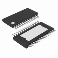
MAX7456EUI+ Maxim Integrated Products, MAX7456EUI+ Datasheet - Page 36

MAX7456EUI+
Manufacturer Part Number
MAX7456EUI+
Description
IC ON-SCREEN DISPLAY 28-TSSOP
Manufacturer
Maxim Integrated Products
Type
OSD (On-Screen Display) Video Generatorr
Datasheet
1.MAX7456EUI.pdf
(44 pages)
Specifications of MAX7456EUI+
Applications
Security Systems, Video Routing
Mounting Type
Surface Mount
Package / Case
28-TSSOP Exposed Pad, 28-eTSSOP, 28-HTSSOP
Current - Supply
58mA
Voltage - Supply
4.75 V ~ 5.25 V
Operating Temperature
-40°C ~ 85°C
Interface
SPI Serial
Display Type
OSD
Digits Or Characters
256 Characters
Maximum Clock Frequency
27 MHz
Operating Supply Voltage
5 V
Maximum Power Dissipation
2162 mW
Maximum Operating Temperature
+ 85 C
Maximum Supply Current
25 mA
Minimum Operating Temperature
- 40 C
Mounting Style
SMD/SMT
Lead Free Status / RoHS Status
Lead free / RoHS Compliant
Configuration
-
Lead Free Status / Rohs Status
Lead free / RoHS Compliant
Single-Channel Monochrome On-Screen
Display with Integrated EEPROM
Write address = 6CH, read address = ECH.
Read/write access: This register contains 4 factory-pre-
set bits [3:0] that must not be changed. Therefore,
Read address = AxH.
Read/write access: read only.
xxxx = Factory preset—can be any one of the 16 possible values. This value is permanently stored in the MAX7456 and will always
be restored to the factory preset value following power-on reset or hardware reset.
NA = Not applicable.
X = Don’t care.
36
BIT
BIT
7–5
0–3
______________________________________________________________________________________
7
6
5
4
3
2
1
0
4
OSD Black Level Register (OSDBL)
DEFAULT
DEFAULT
xxxx
000
NA
NA
NA
NA
NA
NA
NA
NA
1
Status Register (STAT)
Don’t Care
Reset M od e
0 = C l ear w hen p ow er - up r eset m od e i s com p l ete. O ccur s 50m s ( typ ) fol l ow i ng stab l e V
1 = S et w hen i n p ow er - up r eset m od e
Character Memory Status
0 = Available to be written to or read from
1 = Unavailable to be written to or read from
VSYNC Output Level
0 = Active during vertical sync time
1 = Inactive otherwise
HSYNC Output Level
0 = Active during horizontal sync time
1 = Inactive otherwise
Loss-of-Sync (LOS)
0 = Sync Active. Asserted after 32 consecutive input video lines.
1 = No Sync. Asserted after 32 consecutive missing input video lines.
0 = NTSC signal is not detected at VIN
1 = NTSC signal is detected at VIN
0 = PAL signal is not detected at VIN
1 = PAL signal is detected at VIN
Don’t Care
OSD Image Black Level Control
This bit enables the alignment of the OSD image black level with the input image black level at
VOUT. Always enable this bit following power-on reset to ensure the correct OSD image brightness.
0 = Enable automatic OSD black level control
1 = Disable automatic OSD black level control
These bits are factory preset. To ensure proper operation of the MAX7456, do not change the
values of these bits.
when changing bit 4, first read this register, modify bit
4, and then write back the updated byte.
FUNCTION
FUNCTION
D D
( Fi g ur e 22)


