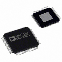
AD8384ASVZ Analog Devices Inc, AD8384ASVZ Datasheet - Page 17

AD8384ASVZ
Manufacturer Part Number
AD8384ASVZ
Description
IC DRIVER LCD 6CH 10BIT 80-TQFP
Manufacturer
Analog Devices Inc
Series
DecDriver™r
Datasheet
1.AD8384ASVZ.pdf
(24 pages)
Specifications of AD8384ASVZ
Display Type
LCD
Interface
3-Wire Serial
Current - Supply
40mA
Voltage - Supply
9 V ~ 18 V
Operating Temperature
0°C ~ 85°C
Mounting Type
Surface Mount
Package / Case
80-TQFP Exposed Pad, 80-eTQFP, 80-HTQFP, 80-VQFP
Lead Free Status / RoHS Status
Lead free / RoHS Compliant
Configuration
-
Digits Or Characters
-
Available stocks
Company
Part Number
Manufacturer
Quantity
Price
Company:
Part Number:
AD8384ASVZ
Manufacturer:
Analog Devices Inc
Quantity:
10 000
APPLICATIONS
POWER SUPPLY SEQUENCING
As indicated under the Absolute Maximum Ratings, the voltage
at any input pin cannot exceed its supply voltage by more than
0.5 V. To ensure compliance with the Absolute Maximum
Ratings, the following power-up and power-down sequencing is
recommended.
During power-up, initial application of nonzero voltages to any
of the input pins must be delayed until the supply voltage ramps
up to at least the highest maximum operational input voltage.
During power-down, the voltage at any input pin must reach
zero during a period not exceeding the hold-up time of the
power supply.
Power ON
Sequence the applied voltages starting with the highest and
proceeding toward the lowest. Apply AVCC and then proceed
with applying the voltages in a decreasing order, for example
VRH, V2, and so on. Apply DVCC last.
Power OFF
Remove voltages starting with the lowest and proceed toward
the highest. Remove DVCC and then proceed with the voltages
in an increasing order, for example V1, V2, VRH, and so on.
Remove AVCC last.
PROCESSOR
IMAGE
DXI, CLXI,
ENBX(1–4)I
CLK
1/3 AD8389
DXxO, CLXxO,
ENBX(1–4)xO
MONITxI
µP
Figure 16. Typical Applications Circuit
Rev. 0 | Page 17 of 24
DB(0:5)
STSQ, XFR,
CLK, R/L, INV
DIRXIN, DIRYIN,
DYIN, CLYIN,
NRGIN
DXIN,
CLXIN,
ENBXIN (1–4)
MONITO
SDI
SCL
SEN
Failure to comply with the Absolute Maximum Ratings may
result in functional failure or damage to the internal ESD
diodes. Damaged ESD diodes may cause temporary parametric
failures, which may result in image artifacts. Damaged ESD
diodes cannot provide full ESD protection, reducing reliability.
To Ensure Grounded Output Mode at Power-Off
If references are active sources:
1.
2.
3.
4.
If references are passive voltage dividers dependent on AVCC:
1.
2.
3.
4.
5.
DC REFERENCE
SVRH, SVRL
VRH, VRL,
VOLTAGES
AD8384
V1, V2,
Program Grounded Output mode
Turn off references
Turn off AVCC
Turn off DVCC
Program Grounded Output mode
Set AVCC to 5 V
Hold for 1 ms
Turn off DVCC
Turn off AVCC
DIRX, DIRY,
DY, CLY,
CLYN, NRG
DX,
CLX, CLXN,
ENBX (1–4)
VID(0:5)
MONITI
VAO1
VAO2
CHANNEL 0–5
LCD TIMING
CONTROLS
LCD TIMING
CONTROLS
MONITOR
VCOM
6-CHANNEL LCD
AD8384


