TC7135CPI Microchip Technology, TC7135CPI Datasheet - Page 5
TC7135CPI
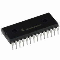
Manufacturer Part Number
TC7135CPI
Description
IC ADC 4 1/2DGT 28-DIP
Manufacturer
Microchip Technology
Datasheet
1.TC7135CPI.pdf
(28 pages)
Specifications of TC7135CPI
Display Type
LED
Configuration
7 Segment
Interface
BCD
Digits Or Characters
A/D 4.5 Digits
Current - Supply
1mA
Voltage - Supply
4 V ~ 6 V
Operating Temperature
0°C ~ 70°C
Mounting Type
Through Hole
Package / Case
28-DIP (0.600", 15.24mm)
Lead Free Status / RoHS Status
Lead free / RoHS Compliant
Other names
158-1133
158-1133
TC7135CPIR
TC7135CPIR
158-1133
TC7135CPIR
TC7135CPIR
Available stocks
Company
Part Number
Manufacturer
Quantity
Price
Company:

Part Number:
TC7135CPI
Manufacturer:
MICROCHIP
Quantity:
12 000
Part Number:
TC7135CPI
Manufacturer:
MICROCHIP/微芯
Quantity:
20 000


2.0
The description of the pins are listed in
TABLE 2-1:
© 2007 Microchip Technology Inc.
28-Pin PLCC
28-Pin PDIP,
Pin Number
10
11
12
13
14
15
16
17
18
19
20
21
22
23
24
25
26
27
28
1
2
3
4
5
6
7
8
9
*
PIN DESCRIPTIONS
Pins not identified or documented are NC (no connects).
44-Pin MQFP*
Pin Number
PIN FUNCTION TABLE
39
40
41
14
15
16
17
18
19
20
25
26
27
28
29
30
31
36
37
38
2
3
4
5
6
7
8
9
64-Pin MQFP*
Pin Number
10
11
12
18
20
22
23
26
28
30
32
38
39
41
42
43
44
45
52
53
54
55
57
58
59
60
7
8
Table
2-1.
ANALOG COMMON
UNDERRANGE
OVERRANGE
RUN/HOLD
BUFF OUT
POLARITY
CLOCK IN
STROBE
INT OUT
Symbol
–INPUT
+INPUT
REF IN
C
C
DGND
BUSY
AZ IN
REF
REF
V–
V+
D5
B1
B2
B4
B8
D4
D3
D2
D1
–
+
Negative power supply input.
External reference input.
Reference point for REF IN.
Integrator output. Integrator capacitor connection.
Auto-zero inpt. Auto-zero capacitor connection.
Analog input buffer output. Integrator resistor
connection.
Reference capacitor input. Reference capacitor
negative connection.
Reference capacitor input. Reference capacitor
positive connection.
Analog input. Analog input negative connection.
Analog input. Analog input positive connection.
Positive power supply input.
Digit drive output. Most Significant Digit (MSD)
Binary Coded Decimal (BCD) output. Least Significant
bit (LSb).
BCD output.
BCD output.
BCD output. Most Significant bit (MSb).
Digit drive output.
Digit drive output.
Digit drive output.
Digit drive output. Least Significant Digit (LSD).
Busy output. At the beginning of the signal-integration
phase, BUSY goes high and remains high until the
first clock pulse after the integrator zero crossing.
Clock input. Conversion clock connection.
Polarity output. A positive input is indicated by a logic
high output. The polarity output is valid at the
beginning of the reference integrate phase and
remains valid until determined during the next
conversion.
Digital logic reference input.
Run/Hold input. When at a logic high, conversions are
performed continuously. A logic low holds the current
data as long as the low condition exists.
Strobe output. The STROBE output pulses low in the
center of the digit drive outputs.
Overrange output. A logic high indicates that the
analog input exceeds the full-scale input range.
Underrange output. A logic high indicates that the
analog input is less than 9% of the full-scale input
range.
Description
TC7135
DS21460D-page 5
Related parts for TC7135CPI
Image
Part Number
Description
Manufacturer
Datasheet
Request
R

Part Number:
Description:
4-1/2 Digit A/d Converter
Manufacturer:
Microchip Technology Inc.
Datasheet:
Part Number:
Description:
Manufacturer:
Microchip Technology Inc.
Datasheet:
Part Number:
Description:
Manufacturer:
Microchip Technology Inc.
Datasheet:
Part Number:
Description:
Manufacturer:
Microchip Technology Inc.
Datasheet:
Part Number:
Description:
Manufacturer:
Microchip Technology Inc.
Datasheet:
Part Number:
Description:
Manufacturer:
Microchip Technology Inc.
Datasheet:
Part Number:
Description:
Manufacturer:
Microchip Technology Inc.
Datasheet:
Part Number:
Description:
Manufacturer:
Microchip Technology Inc.
Datasheet:
Part Number:
Description:
Manufacturer:
Microchip Technology Inc.
Datasheet: