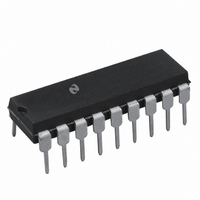
LM3916N National Semiconductor, LM3916N Datasheet - Page 12

LM3916N
Manufacturer Part Number
LM3916N
Description
IC DRIVER DOT BAR DISPLAY 18-DIP
Manufacturer
National Semiconductor
Datasheet
1.LM3916N-1NOPB.pdf
(28 pages)
Specifications of LM3916N
Display Type
LED, LCD, Vacuum Fluorescent
Configuration
Dot/Bar Display
Digits Or Characters
10 Steps
Current - Supply
6.1mA
Voltage - Supply
3 V ~ 25 V
Operating Temperature
0°C ~ 70°C
Mounting Type
Through Hole
Package / Case
18-DIP (0.300", 7.62mm)
Lead Free Status / RoHS Status
Contains lead / RoHS non-compliant
Interface
-
Other names
*LM3916N
LM3916
LM3916
Available stocks
Company
Part Number
Manufacturer
Quantity
Price
Part Number:
LM3916N
Manufacturer:
NS/国半
Quantity:
20 000
Company:
Part Number:
LM3916N-1
Manufacturer:
TI
Quantity:
2 100
Part Number:
LM3916N-1
Manufacturer:
NS/国半
Quantity:
20 000
www.national.com
Application Hints
damped second order response with a resonant frequency
Design Equations
Peak Program Meter
The VU meter, originally intended for signals sent via tele-
phone lines, has shortcomings when used in high fidelity
systems. Due to its slow response time, a VU meter will not
accurately display transients that can saturate a magnetic
tape or drive an amplifier into clipping. The fast-attack peak
program meter (PPM) which does not have this problem is
becoming increasingly popular.
While several European organizations have specifications
for peak program meters, the German DIN specification
45406 is becoming a de facto standard. Rather than respond
instantaneously to peak, however, PPM specifications re-
quire a finite “integration time” so that only peaks wide
enough to be audible are displayed. DIN 45406 calls for a
response of 1 dB down from steady-state for a 10 ms tone
burst and 4 dB down for a 3 ms tone burst. These require-
ments are consistent with the other frequently encountered
spec of 2 dB down for a 5 ms burst and are met by an attack
time constant of 1.7 ms.
FIGURE 7. Full-Wave Average Detector to VU Meter Specifications*
(Continued)
GAIN
10
1
100k
R5
1M
100k
43k
12
R6
of 2.1 Hz and a Q of 0.62. Figure 7 depicts a simple rectifier/
filter circuit that meets these criteria.
The specified return time of 1.5s to −20 dB requires a
650 ms decay time constant. The full-wave peak detector of
Figure 6 satisfies both the attack and decay time criteria.
Cascading The LM3916
The LM3916 by itself covers the 23 dB range of the conven-
tional VU meter. To display signals of 40 dB or 70 dB
dynamic range, the LM3916 may be cascaded with the 3
dB/step LM3915s. Alternatively, two LM3916s may be cas-
caded for increased resolution over a 28 dB range. Refer to
the Extended Range VU Meter and High Resolution VU
Meter in the Typical Applications section for the complete
circuits for both dot and bar mode displays.
To obtain a display that makes sense when an LM3915 and
an LM3916 are cascaded, the −20 dB output from the
LM3916 is dropped. The full-scale display for the LM3915 is
set at 3 dB below the LM3916’s −10 dB output and the rest
of the thresholds continue the 3 dB/step spacing. A simple,
low cost approach is to set the reference voltage of the two
chips 16 dB apart as in Figure 5. The LM3915, with pin 8
grounded, runs at 1.25V full-scale. R1 and R2 set the
C2
2.0
1.0
0.056 µF
0.56 µF
C3
00797114


