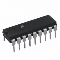
LM3916N National Semiconductor, LM3916N Datasheet - Page 14

LM3916N
Manufacturer Part Number
LM3916N
Description
IC DRIVER DOT BAR DISPLAY 18-DIP
Manufacturer
National Semiconductor
Datasheet
1.LM3916N-1NOPB.pdf
(28 pages)
Specifications of LM3916N
Display Type
LED, LCD, Vacuum Fluorescent
Configuration
Dot/Bar Display
Digits Or Characters
10 Steps
Current - Supply
6.1mA
Voltage - Supply
3 V ~ 25 V
Operating Temperature
0°C ~ 70°C
Mounting Type
Through Hole
Package / Case
18-DIP (0.300", 7.62mm)
Lead Free Status / RoHS Status
Contains lead / RoHS non-compliant
Interface
-
Other names
*LM3916N
LM3916
LM3916
Available stocks
Company
Part Number
Manufacturer
Quantity
Price
Part Number:
LM3916N
Manufacturer:
NS/国半
Quantity:
20 000
Company:
Part Number:
LM3916N-1
Manufacturer:
TI
Quantity:
2 100
Part Number:
LM3916N-1
Manufacturer:
NS/国半
Quantity:
20 000
www.national.com
Application Hints
To extend this approach to get a 70 dB display, another
30 dB of amplification must be placed in the signal path
ahead of the lowest LM3915. Extreme care is required as the
lowest LM3915 displays input signals down to 2 mV! Several
offset nulls may be required. High currents should not share
the same path as the low level signal. Also power line wiring
should be kept away from signal lines.
TIPS ON REFERENCE VOLTAGE AND LED CURRENT
PROGRAMMING
Single Driver
The equations in Figure 10 illustrate how to choose resistor
values to set reference voltage for the simple case where no
LED intensity adjustment is required. A LED current of
10 mA to 20 mA generally produces adequate illumination.
Having 10V full-scale across the internal voltage divider
gives best accuracy by keeping signal level high relative to
the offset voltage of the internal comparators. However, this
causes 1 mA to flow from pin 7 into the divider which means
that the LED current will be at least 10 mA. R1 will typically
be between 1 kΩ and 5 kΩ. To trim the reference voltage,
vary R2.
The current in Figure 11 shows how to add a LED intensity
control which can vary LED current from 5 mA to 28 mA.
Choosing V
increasing the intensity adjustment range. The reference
adjustment has some effect on LED intensity but the reverse
is not true.
FIGURE 10. Design Equations for Fixed LED Intensity
REF
= 5V lowers the current drawn by the ladder,
(Continued)
00797117
14
5 mA ≤ I
Multiple Drivers
Figure 12 shows how to obtain a common reference trim and
intensity control for two drivers. The two ICs may be con-
nected in cascade or may be handling separate channels for
stereo. This technique can be extended for larger numbers
of drivers by varying the values of R1, R2 and R3. Because
the LM3915 has a greater ladder resistance, R5 was picked
less than R7 in such a way as to provide equal reference
load currents. The ICs’ internal references track within
100 mV so that worst case error from chip to chip is only 0.2
dB for V
The scheme in Figure 13 is useful when the reference and
LED intensity must be adjusted independently over a wide
range. The R
with no effect on LED current. Since the internal divider here
does not load down the reference, minimum LED current is
much lower. At the minimum recommended reference load
of 80 µA, LED current is about 0.8 mA. The resistor values
shown give a LED current range from 1.5 mA to 25 mA.
At the low end of the intensity adjustment, the voltage drop
across the 510Ω current-sharing resistors is so small that
chip to chip variation in reference voltage may yield a visible
variation in LED intensity. The optional approach shown of
connecting the bottom end of the intensity control pot to a
negative supply overcomes this problem by allowing a larger
voltage drop across the (larger) current-sharing resistors.
LED
REF
≤ 28 mA
FIGURE 11. Varying LED Intensity
= 5V.
HI
voltage can be adjusted from 1.2V to 10V
@
V
REF
= 5V
00797118


