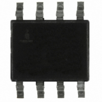
ISL6141CB Intersil, ISL6141CB Datasheet - Page 16

ISL6141CB
Manufacturer Part Number
ISL6141CB
Description
IC CONTROLLER HOT PLUG 8-SOIC
Manufacturer
Intersil
Type
Hot-Swap Controllerr
Datasheet
1.ISL6151CBZA.pdf
(19 pages)
Specifications of ISL6141CB
Applications
General Purpose, VoIP
Internal Switch(s)
No
Voltage - Supply
36 V ~ 72 V
Operating Temperature
0°C ~ 70°C
Mounting Type
Surface Mount
Package / Case
8-SOIC (0.154", 3.90mm Width)
Linear Misc Type
Negative Voltage
Package Type
SOIC N
Operating Supply Voltage (max)
80V
Operating Temperature (min)
0C
Operating Temperature (max)
70C
Operating Temperature Classification
Commercial
Product Depth (mm)
4mm
Product Height (mm)
1.5mm
Product Length (mm)
5mm
Mounting
Surface Mount
Pin Count
8
Lead Free Status / RoHS Status
Contains lead / RoHS non-compliant
Available stocks
Company
Part Number
Manufacturer
Quantity
Price
Company:
Part Number:
ISL6141CB-T
Manufacturer:
LSIOGIC
Quantity:
218
Part Number:
ISL6141CBZ
Manufacturer:
INTERSIL
Quantity:
20 000
When any of the 4 conditions occur that turn off the GATE
(OV, UV, UVLO, Over-Current Time-Out) the PWRGD latch
is reset and the Q2 DMOS device will shut off (high
impedance). The pin will quickly be pulled high by the
external module (or an optional pull-up resistor or equivalent)
which in turn will disable it. If a pull-up resistor is used, it can
be connected to any supply voltage that doesn’t exceed the
IC pin maximum ratings on the high end, but is high enough
to give acceptable logic levels to whatever signal it is driving.
An external clamp may be used to limit the voltage range.
The PWRGD can also drive an opto-coupler (such as a
4N25), as shown in Figure 31 or LED (Figure 32). In both
cases, they are on (active) when power is good. Resistors
R12 or R13 are chosen, based on the supply voltage, and
the amount of current needed by the loads.
ISL6151 (H version; Figure 33): Under normal conditions
(DRAIN voltage - V
the Q3 DMOS will be on, shorting the bottom of the internal
resistor to V
the external module is high enough, the voltage drop across
the 6.2kΩ resistor will look like a logic high (relative to
DRAIN). Note that the module is only referenced to DRAIN,
not V
DRAIN and V
When any of the 4 conditions occur that turn off the GATE,
the Q3 DMOS turns off, and the resistor and Q2 clamp the
PWRGD pin to one diode drop (~0.7V) above the DRAIN
∆ V
GATE
GATE
∆ V
GATE
FIGURE 31. ACTIVE LOW ENABLE OPTO-ISOLATOR
EE
V
GATE
V
+
EE
-
FIGURE 32. ACTIVE LOW ENABLE WITH LED
V
PG
(but under normal conditions, the FET is on, and the
V
GH
EE
V
+
-
V
PG
GH
EE
EE
(SECTION OF) ISL6141
+
+
-
-
, and turning Q2 off. If the pull-up current from
V
+
+
(SECTION OF) ISL6141
-
-
are almost the same voltage).
DD
V
(L VERSION)
EE
DD
(L VERSION)
LATCH
< V
LOGIC
+
LATCH
LOGIC
PG
+
16
, and ∆V
Q2
V
EE
Q2
V
EE
PWRGD
GATE
DRAIN
PWRGD
DRAIN
- V
GATE
R12
OPTO
R13
LED (GREEN)
< V
ISL6141, ISL6151
PWRGD
GH
),
pin. This should be able to pull low against the module pull-
up current, and disable the module.
Applications: GATE pin
To help protect the external FET, the output of the GATE pin
is internally clamped; up to an 80V supply and will not be any
higher than 15V. Under normal operation when the supply
voltage is above 20V, the GATE voltage will be regulated to a
nominal 13.6V above V
Applications: “Brick” Regulators
One of the typical loads used are DC/DC regulators, some
commonly known as “brick” regulators, (partly due to their
shape, and because it can be considered a “building block”
of a system). For a given input voltage range, there are
usually whole families of different output voltages and
current ranges. There are also various standardized sizes
and pinouts, starting with the original “full” brick, and since
getting smaller (half-bricks and quarter-bricks are now
common).
Other common features may include: all components (except
some filter capacitors) are self-contained in a molded plastic
package; external pins for connections; and often an
ENABLE input pin to turn it on or off. A hot plug IC, such as
the ISL6141 is often used to gate power to a brick, as well as
turn it on.
Many bricks have both logic polarities available (Enable Hi or
Lo input); select the ISL6141 (L version) and ISL6151 (H
version) to match. There is little difference between them,
although the L version output is usually simpler to interface.
The Enable input often has a pull-up resistor or current
source, or equivalent built in; care must be taken in the
ISL6151 (H version) output that the given current will create
a high enough input voltage (remember that current through
the RPG 6.2kΩ resistor generates the high voltage level; see
Figure 33).
The input capacitance of the brick is chosen to match its
system requirements, such as filtering noise, and
maintaining regulation under varying loads. Note that this
input capacitance appears as the load capacitance of the
ISL6141/51.
∆ V
GATE
GATE
V
V
EE
+
-
V
PG
GH
FIGURE 33. ACTIVE HIGH ENABLE MODULE
(SECTION OF) ISL6151
+
+
-
-
VDD
(H VERSION)
LATCH
LOGIC
+
EE
.
RPG
6.2K
Q3
V
EE
Q2
PWRGD
DRAIN
CL
+
VIN+
ACTIVE HIGH
VIN-
ON/OFF
MODULE
ENABLE
VOUT+
VOUT-


