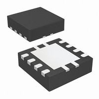
STLD40DPUR STMicroelectronics, STLD40DPUR Datasheet

STLD40DPUR
Specifications of STLD40DPUR
Available stocks
Related parts for STLD40DPUR
STLD40DPUR Summary of contents
Page 1
... The output current capability with an output voltage Table 1. Device summary Order code STLD40DPUR July 2010 QFN8 ( mm) The regulation is done by sensing the LED current through the resistor R The device can be turned ON/OFF through the logic enable signal pin EN ...
Page 2
Contents Contents 1 Block diagram . . . . . . . . . . . . . . . . . . . . . . . . . . . . . . . . . . . ...
Page 3
STLD40D Block diagram 1 Figure 1. Block diagram Doc ID 12203 Rev 6 Block diagram 3/16 ...
Page 4
Pin configuration 2 Pin configuration Figure 2. Pin connections (top through view) Table 2. Pin description Pin n° Symbol 1 V Supply voltage I 2 RSET Peak inductor current adjust 3 GND Analog ground 4 FB Feedback for the LED ...
Page 5
STLD40D 3 Maximum ratings Table 3. Absolute maximum ratings Symbol VB VB Breakdown voltage Maximum voltage applied on pin EN V Supply voltage range I V ESD ratings - (HBM MIL STD 883C) ESD T ...
Page 6
Electrical characteristics 4 Electrical characteristics ° ° typ. values @ 25 °C, unless otherwise specified. O Table 5. Electrical characteristics Symbol Parameter V Input voltage range I V ...
Page 7
STLD40D 5 Functional description 5.1 Boost controller The STLD40D is a boost converter operating in PFM (pulsed frequency modulation) mode. The converter monitors the LED current through the resistor R voltage falls below the reference voltage REF2, the boost switch ...
Page 8
Typical application 6 Typical application Figure 3. Application circuit Table 6. External component proposal (see Symbol Parameter D Boost schottky diode Feedback LED current regulation R LED resistor R Current peak setting resistor SET C Input filtering capacitor I Output ...
Page 9
STLD40D 7 Typical performance characteristics load ( typ. values @ 25 °C, unless otherwise specified. O Figure 4. I vs. R LED LED Figure 6. I ...
Page 10
Typical performance characteristics Figure 10. V vs. temperature FB Figure 12. Efficiency vs. V Figure 14. I vs. duty cycle EN pin LED (dimming) 10/16 Figure 11. V Figure 13 Doc ID 12203 Rev 6 STLD40D vs. temperature ...
Page 11
STLD40D 8 Package mechanical data In order to meet environmental requirements, ST offers these devices in different grades of ® ECOPACK packages, depending on their level of environmental compliance. ECOPACK specifications, grade definitions and product status are available at: www.st.com. ...
Page 12
Package mechanical data Figure 15. Drawing dimension QFN8 ( mm) 12/16 Doc ID 12203 Rev 6 STLD40D 8057023_B ...
Page 13
STLD40D Tape & reel QFNxx/DFNxx (3x3) mechanical data Dim. Min 12 mm. Typ. Max. Min. 180 13.2 0.504 0.795 2.362 14.4 3.3 3.3 1 Doc ID ...
Page 14
Package mechanical data Figure 16. QFN8 (3x3) footprint recommended data 14/16 Doc ID 12203 Rev 6 STLD40D ...
Page 15
STLD40D 9 Revision history Table 8. Document revision history Date Revision 20-Mar-2006 1 04-Apr-2006 2 27-Feb-2009 3 03-Mar-2009 4 11-Mar-2009 5 01-Jul-2010 6 Initial release. Add R in table 4 and fig 2 has been updated. SET Modified mechanical data. ...
Page 16
... Information in this document is provided solely in connection with ST products. STMicroelectronics NV and its subsidiaries (“ST”) reserve the right to make changes, corrections, modifications or improvements, to this document, and the products and services described herein at any time, without notice. All ST products are sold pursuant to ST’s terms and conditions of sale. ...


