LP5520TL/NOPB National Semiconductor, LP5520TL/NOPB Datasheet - Page 26
LP5520TL/NOPB
Manufacturer Part Number
LP5520TL/NOPB
Description
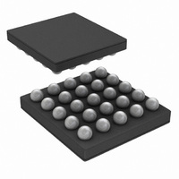
IC LED DRIVER RGB 25-USMD
Manufacturer
National Semiconductor
Series
PowerWise®r
Type
RGB LED Driverr
Datasheet
1.LP5520TLNOPB.pdf
(34 pages)
Specifications of LP5520TL/NOPB
Constant Current
Yes
Topology
PWM, Step-Up (Boost)
Number Of Outputs
3
Internal Driver
Yes
Type - Primary
Backlight, Light Management Unit (LMU)
Type - Secondary
RGB, White LED
Frequency
1.22kHz, 19.52kHz
Voltage - Supply
2.9 V ~ 5.5 V
Voltage - Output
5 V ~ 20 V
Mounting Type
Surface Mount
Package / Case
25-MicroSMD
Operating Temperature
-30°C ~ 85°C
Current - Output / Channel
60mA
Internal Switch(s)
Yes
Efficiency
87%
Lead Free Status / RoHS Status
Lead free / RoHS Compliant
Other names
LP5520TLTR


www.national.com
Recommended External Components
OUTPUT CAPACITOR: C
The output capacitor C
the output ripple voltage. In general, the higher the value of
C
ramic capacitors with low ESR are the best choice. Capacitor
voltage rating must be sufficient, 25V or greater is recom-
mended. Examples of suitable capacitors are: TDK
C3216X5R1E475K, Panasonic ECJ3YB1E475K and ECJ4Y-
B1E475K.
Some ceramic capacitors, especially those in small pack-
ages, exhibit a strong capacitance reduction with the in-
creased applied voltage (DC bias effect). The capacitance
value can fall below half of the nominal capacitance. Too low
output capacitance can make the boost converter unstable.
Output capacitor value reduction due to DC bias should be
less than 70% at 20V (minimum 3 µF of real capacitance re-
maining).
INPUT CAPACITOR: C
The input capacitor C
input ripple voltage and to a lesser degree the V
higher value C
OUTPUT DIODE: D
A schottky diode should be used for the output diode. To
maintain high efficiency the average current rating of the
schottky diode should be greater than the peak inductor cur-
rent (1A). Schottky diodes with a low forward drop and fast
switching speeds are ideal for increasing efficiency in portable
applications. Choose a reverse breakdown voltage of the
schottky diode significantly larger (~30V) than the output volt-
age. Do not use ordinary rectifier diodes, since slow switching
speeds and long recovery times cause the efficiency and the
LIST OF RECOMMENDED EXTERNAL COMPONENTS
OUT
Symbol
C
C
C
C
LEDs
C
C
R
C
L
VDDIO
C
VDDA
VDDD
VLDO
D
L
OUT
, the lower the output ripple magnitude. Multilayer ce-
SW
SW
SW
HF
IN
1
1
IN
Symbol Explanation
C between V
C between V
C between V
C between VDDIO and GND
C between FB and GND
C between battery voltage and GND
L between SW and V
Rectifying Diode (Vf @ maxload)
Optional C in EMI filter
Optional R in EMI filter
Optional high frequency output C
Ferrite bead in SW pin
will give a lower V
OUT
IN
OUT
IN
directly affects the magnitude of the
OUT
directly affects the magnitude of
DDA
DDD
LDO
and GND
and GND
and GND
IN
BAT
ripple.
OUT
ripple. A
26
load regulation to suffer. A schottky diode with low parasitic
capacitance helps in reducing EMI noise. Examples of suit-
able diodes are: Central Semiconductor CMMSH1-40 and
Infineon BAS52-02V.
EMI FILTER COMPONENTS: C
EMI filter (R
to slow down the fast switching edges and reduce ringing.
These components should be as near as possible to the SW
pin to ensure reliable operation. High frequency capacitor
(C
quency noise from the switcher. 50V or greater voltage rating
is recommended for the capacitors. The ferrite bead DC re-
sistance should be less than 0.1Ω and current rating 1A or
above. The impedance at 100 MHz should be 30 – 300Ω.
Examples of suitable types are TDK MPZ1608S101A and
Taiyo-Yuden FBMH 1608HM600-T.
INDUCTOR: L
A 4.7 µH shielded inductor is suggested for LP5520 boost
converter. The inductor should have a saturation current rat-
ing higher than the peak current it will experience during
circuit operation (0.5 – 1.0A depending on the output current).
Less than 500 mΩ ESR is suggested for high efficiency. Open
core inductors cause flux linkage with circuit components and
interfere with the normal operation of the circuit. This should
be avoided. For high efficiency, choose an inductor with a high
frequency core material such as ferrite to reduce the core
losses. To minimize radiated noise, use a toroid, pot core or
shielded core inductor. The inductor should be connected to
the SW pin as close to the IC as possible. Examples of suit-
able inductors are: TDK VLF3010AT-4R7MR70 and Coilcraft
LPS3010-472NL.
0. 3 - 0.5
33 - 100
30 - 300
2 x 4.7
SW
Value
100
100
100
330
4.7
3.9
10
1
) in the boost output helps in suppressing the high fre-
SW
at 100 Mhz
, C
1
SW
Unit
µH
nF
nF
µF
nF
µF
µF
pF
pF
V
Ω
Ω
and L
User Defined
SW
Ceramic, X7R / X5R
Ceramic, X7R, X5R
Ceramic, X7R / X5R
Ceramic, X7R / X5R
Ceramic, X7R / X5R, tolerance
±10%, DC bias effect ~ –30% at
20V
Ceramic, X7R / X5R
Shielded, low ESR, I
Schottky diode, reverse voltage
30V, repetitive peak current 0.5A
Ceramic, X7R / X5R, 50V
±1%
Ceramic, X7R, X5R, 50V
) on the SW pin may be needed
SW
, R
SW
, L
Type
SW
and C
SAT
0.5A
HF
Related parts for LP5520TL/NOPB
Image
Part Number
Description
Manufacturer
Datasheet
Request
R

Part Number:
Description:
RGB Backlight LED Driver
Manufacturer:
NSC [National Semiconductor]
Datasheet:

Part Number:
Description:
National Semiconductor [8-Bit D/A Converter]
Manufacturer:
National Semiconductor
Datasheet:
Part Number:
Description:
National Semiconductor [Media Coprocessor]
Manufacturer:
National Semiconductor
Datasheet:
Part Number:
Description:
Digitally Controlled Tone and Volume Circuit with Stereo Audio Power Amplifier, Microphone Preamp Stage and National 3D Sound
Manufacturer:
National Semiconductor
Datasheet:
Part Number:
Description:
Digitally Controlled Tone and Volume Circuit with Stereo Audio Power Amplifier, Microphone Preamp Stage and National 3D Sound
Manufacturer:
National Semiconductor
Datasheet:
Part Number:
Description:
AC97 Rev 2 Codec with Sample Rate Conversion and National 3D Sound
Manufacturer:
National Semiconductor
Part Number:
Description:
Manufacturer:
National Semiconductor
Datasheet:
Part Number:
Description:
Manufacturer:
National Semiconductor
Datasheet:
Part Number:
Description:
General Purpose, Low Voltage, Low Power, Rail-to-Rail Output Operational Amplifiers
Manufacturer:
National Semiconductor
Datasheet:
Part Number:
Description:
8-bit 20 MSPS flash A/D converter.
Manufacturer:
National Semiconductor
Datasheet:
Part Number:
Description:
Low Noise Quad Operational Amplifier
Manufacturer:
National Semiconductor
Datasheet:
Part Number:
Description:
Quad Differential Line Receivers
Manufacturer:
National Semiconductor
Datasheet:
Part Number:
Description:
Quad High Speed Trapezoidal? Bus Transceiver
Manufacturer:
National Semiconductor
Datasheet:
Part Number:
Description:
Dual Line Receiver
Manufacturer:
National Semiconductor
Datasheet: