LP5521TMX/NOPB National Semiconductor, LP5521TMX/NOPB Datasheet - Page 21
LP5521TMX/NOPB
Manufacturer Part Number
LP5521TMX/NOPB
Description
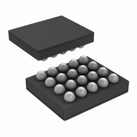
IC LED DRIVER RGB 25-USMD
Manufacturer
National Semiconductor
Series
PowerWise®r
Type
RGB LED Driverr
Datasheet
1.LP5521TMNOPB.pdf
(40 pages)
Specifications of LP5521TMX/NOPB
Constant Current
Yes
Topology
PWM, Switched Capacitor (Charge Pump)
Number Of Outputs
3
Internal Driver
Yes
Type - Primary
Backlight, Light Management Unit (LMU)
Type - Secondary
RGB
Frequency
1.25MHz
Voltage - Supply
2.7 V ~ 5.5 V
Voltage - Output
4.55V
Mounting Type
Surface Mount
Package / Case
20-MicroSMD
Operating Temperature
-30°C ~ 85°C
Current - Output / Channel
25.5mA
Internal Switch(s)
Yes
Efficiency
95%
Lead Free Status / RoHS Status
Lead free / RoHS Compliant
Other names
LP5521TMX
Available stocks
Company
Part Number
Manufacturer
Quantity
Price
Company:

Part Number:
LP5521TMX/NOPB
Manufacturer:
TI
Quantity:
57 001
Part Number:
LP5521TMX/NOPB
Manufacturer:
TI/德州仪器
Quantity:
20 000


X means do not care whether 1 or 0.
Trigger
Wait or send triggers can be used to e.g. synchronize opera-
tion between different channels. Send trigger command takes
sixteen 32 kHz clock cycles and wait for trigger takes at least
sixteen 32 kHz clock cycles. The receiving channel stores
sent triggers. Received triggers are cleared by wait for trigger
command if received triggers match to channels defined in
the command. Channel waits for until all defined triggers have
been received.
External trigger input signal must be at least two 32 kHz clock
cycles (= 61 μs typ.) long to be recognized. Trigger output
X means do not care whether 1 or 0.
15
1
14
1
send trigger<5:0>
wait trigger<5:0>
13
1
Name
Name
reset
int
EXT
12
11
Value
Value(d)
0
1
0
1
wait trigger <5:0>
X
0-31
0-31
10
No interrupt will be sent.
Send interrupt to processor by pulling the INT pin down and
setting corresponding status register bit high to notify that
program has ended. Interrupt can only be cleared by reading
interrupt status register 0CH.
Keep the current PWM value.
Set PWM value to 0.
B
9
Wait for trigger for the channel(s) defined. Several triggers can
be defined in the same command. Bit 0 is R, bit 1 is G, bit 2 is B
and bit 5 is external trigger I/O. Bits 3 and 4 are not in use.
Send trigger for the channel(s) defined. Several triggers can be
defined in the same command. Bit 0 is R, bit 1 is G, bit 2 is B and
bit 5 is external trigger I/O. Bits 3 and 4 are not in use.
Trigger command
G
8
21
R
7
signal is three 32 kHz clock cycles (92 μs typ.) long. External
trigger signal is active low, i.e. when trigger is sent/received
the pin is pulled to GND. Sent external trigger is masked, i.e.
the device which has sent the trigger will not recognize it. If
send and wait external trigger are used on the same com-
mand, the send external trigger is executed first, then the wait
external trigger.
Description
EXT
6
Description
5
send trigger <5:0>
X
4
B
3
G
2
R
1
www.national.com
X
0
Related parts for LP5521TMX/NOPB
Image
Part Number
Description
Manufacturer
Datasheet
Request
R

Part Number:
Description:
Manufacturer:
National Semiconductor
Datasheet:

Part Number:
Description:
IC LED DRIVER RGB 25-USMD
Manufacturer:
National Semiconductor
Datasheet:

Part Number:
Description:
Programmable Three Channel LED Driver
Manufacturer:
NSC [National Semiconductor]
Datasheet:
Part Number:
Description:
National Semiconductor [8-Bit D/A Converter]
Manufacturer:
National Semiconductor
Datasheet:
Part Number:
Description:
National Semiconductor [Media Coprocessor]
Manufacturer:
National Semiconductor
Datasheet:
Part Number:
Description:
Digitally Controlled Tone and Volume Circuit with Stereo Audio Power Amplifier, Microphone Preamp Stage and National 3D Sound
Manufacturer:
National Semiconductor
Datasheet:
Part Number:
Description:
Digitally Controlled Tone and Volume Circuit with Stereo Audio Power Amplifier, Microphone Preamp Stage and National 3D Sound
Manufacturer:
National Semiconductor
Datasheet:
Part Number:
Description:
AC97 Rev 2 Codec with Sample Rate Conversion and National 3D Sound
Manufacturer:
National Semiconductor
Part Number:
Description:
Manufacturer:
National Semiconductor
Datasheet:
Part Number:
Description:
Manufacturer:
National Semiconductor
Datasheet:
Part Number:
Description:
General Purpose, Low Voltage, Low Power, Rail-to-Rail Output Operational Amplifiers
Manufacturer:
National Semiconductor
Datasheet:
Part Number:
Description:
8-bit 20 MSPS flash A/D converter.
Manufacturer:
National Semiconductor
Datasheet:
Part Number:
Description:
Low Noise Quad Operational Amplifier
Manufacturer:
National Semiconductor
Datasheet:
Part Number:
Description:
Quad Differential Line Receivers
Manufacturer:
National Semiconductor
Datasheet: