LP5521TMX/NOPB National Semiconductor, LP5521TMX/NOPB Datasheet - Page 22
LP5521TMX/NOPB
Manufacturer Part Number
LP5521TMX/NOPB
Description
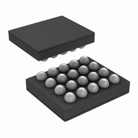
IC LED DRIVER RGB 25-USMD
Manufacturer
National Semiconductor
Series
PowerWise®r
Type
RGB LED Driverr
Datasheet
1.LP5521TMNOPB.pdf
(40 pages)
Specifications of LP5521TMX/NOPB
Constant Current
Yes
Topology
PWM, Switched Capacitor (Charge Pump)
Number Of Outputs
3
Internal Driver
Yes
Type - Primary
Backlight, Light Management Unit (LMU)
Type - Secondary
RGB
Frequency
1.25MHz
Voltage - Supply
2.7 V ~ 5.5 V
Voltage - Output
4.55V
Mounting Type
Surface Mount
Package / Case
20-MicroSMD
Operating Temperature
-30°C ~ 85°C
Current - Output / Channel
25.5mA
Internal Switch(s)
Yes
Efficiency
95%
Lead Free Status / RoHS Status
Lead free / RoHS Compliant
Other names
LP5521TMX
Available stocks
Company
Part Number
Manufacturer
Quantity
Price
Company:

Part Number:
LP5521TMX/NOPB
Manufacturer:
TI
Quantity:
57 001
Part Number:
LP5521TMX/NOPB
Manufacturer:
TI/德州仪器
Quantity:
20 000


www.national.com
Power Save Mode
Automatic
PWRSAVE_EN bit in register address 08H is 1. Almost all
analog blocks are powered down in power save, if external
clock is used. Only charge pump protection circuits remain
active. However if internal clock has been selected only
charge pump and led drivers are disabled during power save
since digital part of the LED controller need to remain active.
In both cases charge pump enters 'weak 1x' mode. In this
mode charge pump utilizes a passive current limited keep-
alive switch, which keeps the output voltage at battery level.
See application note "LP5521 Power Efficiency Considerations" for more information.
External Clock Detection
The presence of external clock can be detected by the
LP5521. Program execution is clocked with internal 32 kHz
clock or with external clock. Clocking is controlled with regis-
ter address 08H bits, INT_CLK_EN and CLK_DET_EN as
seen on the following table.
External clock can be used if clock is present at CLK_32K pin.
External clock frequency must be 32 kHz for the program ex-
ecution / PWM timing to be like specified. If higher or lower
frequency is used, it will affect the program engine execution
speed. If other than 32kHz clock frequency is used, the pro-
gram execution timings must be scaled accordingly. The
external clock detector block only detects too low clock fre-
quency (<15 kHz). If external clock frequency is higher than
power
LED controller operation
mode (R,G,B_MODE)
save
Other commands
CLK_DET_EN,
INT_CLK_EN
Command
Set PWM
Trigger
Name
Ramp
Wait
End
00b
01b
10b
11b
mode
is
enabled
1:0
Bit
Disabled mode enables power save
Load program to SRAM mode prevents power save
Run program mode enables power save if there is no PWM
activity and command look-ahead filter condition is met
Direct control mode enables power save if there is no PWM
activity
No PWM activity and current command wait time longer than 50
ms. If prescale = 1 then wait time needs to be longer than 80 ms.
Ramp Command PWM value reaches minimum 0 and current
command execution time left more than 50 ms. If prescale = 1
then time left needs to be more than 80 ms.
No PWM activity during wait for trigger command execution.
No PWM activity or Reset bit = 1
Enables power save if PWM set to 0 and next command
generates at least 50 ms wait
No effect to power save
CONFIG register (08H):
when
LED Controller clock source
00b = External clock source (CLK_32K)
01b = Internal clock
10b = Automatic selection
11b = Internal clock
22
During program execution LP5521 can enter power save if
there is no PWM activity in R, G and B outputs. To prevent
short power save sequences during program execution,
LP5521 has command look-ahead filter. In every instruction
cycle R, G, B commands are analyzed, and if there is suffi-
cient time left with no PWM activity, device will enter power
save. In power save program execution continues uninter-
ruptedly. When a command that requires PWM activity is
executed, fast internal start-up sequence will be started au-
tomatically. Following tables describe commands and condi-
tions that can activate power save. All channels (R,G,B) need
to meet power save condition in order to enable power save.
specified, the external clock detector notifies that external
clock is present. External clock status can be checked with
read only bit EXT_CLK_USED in register address 0CH, when
the external clock detection is enabled (CLK_DET_EN bit =
high). If EXT_CLK_USED = 1, then the external clock is de-
tected and it is used for timing, if automatic clock selection is
enabled (see table below).
If external clock is stuck-at-zero or stuck-at-one, or the clock
frequency is too low, the clock detector indicates that external
clock is not present.
If external clock is not used on the application, CLK_32K pin
should be connected to GND to prevent floating of this pin and
extra current consumption.
Power save condition
Power save condition
Description
Related parts for LP5521TMX/NOPB
Image
Part Number
Description
Manufacturer
Datasheet
Request
R

Part Number:
Description:
Manufacturer:
National Semiconductor
Datasheet:

Part Number:
Description:
IC LED DRIVER RGB 25-USMD
Manufacturer:
National Semiconductor
Datasheet:

Part Number:
Description:
Programmable Three Channel LED Driver
Manufacturer:
NSC [National Semiconductor]
Datasheet:
Part Number:
Description:
National Semiconductor [8-Bit D/A Converter]
Manufacturer:
National Semiconductor
Datasheet:
Part Number:
Description:
National Semiconductor [Media Coprocessor]
Manufacturer:
National Semiconductor
Datasheet:
Part Number:
Description:
Digitally Controlled Tone and Volume Circuit with Stereo Audio Power Amplifier, Microphone Preamp Stage and National 3D Sound
Manufacturer:
National Semiconductor
Datasheet:
Part Number:
Description:
Digitally Controlled Tone and Volume Circuit with Stereo Audio Power Amplifier, Microphone Preamp Stage and National 3D Sound
Manufacturer:
National Semiconductor
Datasheet:
Part Number:
Description:
AC97 Rev 2 Codec with Sample Rate Conversion and National 3D Sound
Manufacturer:
National Semiconductor
Part Number:
Description:
Manufacturer:
National Semiconductor
Datasheet:
Part Number:
Description:
Manufacturer:
National Semiconductor
Datasheet:
Part Number:
Description:
General Purpose, Low Voltage, Low Power, Rail-to-Rail Output Operational Amplifiers
Manufacturer:
National Semiconductor
Datasheet:
Part Number:
Description:
8-bit 20 MSPS flash A/D converter.
Manufacturer:
National Semiconductor
Datasheet:
Part Number:
Description:
Low Noise Quad Operational Amplifier
Manufacturer:
National Semiconductor
Datasheet:
Part Number:
Description:
Quad Differential Line Receivers
Manufacturer:
National Semiconductor
Datasheet: