LP5521TMX/NOPB National Semiconductor, LP5521TMX/NOPB Datasheet - Page 25
LP5521TMX/NOPB
Manufacturer Part Number
LP5521TMX/NOPB
Description
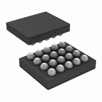
IC LED DRIVER RGB 25-USMD
Manufacturer
National Semiconductor
Series
PowerWise®r
Type
RGB LED Driverr
Datasheet
1.LP5521TMNOPB.pdf
(40 pages)
Specifications of LP5521TMX/NOPB
Constant Current
Yes
Topology
PWM, Switched Capacitor (Charge Pump)
Number Of Outputs
3
Internal Driver
Yes
Type - Primary
Backlight, Light Management Unit (LMU)
Type - Secondary
RGB
Frequency
1.25MHz
Voltage - Supply
2.7 V ~ 5.5 V
Voltage - Output
4.55V
Mounting Type
Surface Mount
Package / Case
20-MicroSMD
Operating Temperature
-30°C ~ 85°C
Current - Output / Channel
25.5mA
Internal Switch(s)
Yes
Efficiency
95%
Lead Free Status / RoHS Status
Lead free / RoHS Compliant
Other names
LP5521TMX
Available stocks
Company
Part Number
Manufacturer
Quantity
Price
Company:

Part Number:
LP5521TMX/NOPB
Manufacturer:
TI
Quantity:
57 001
Part Number:
LP5521TMX/NOPB
Manufacturer:
TI/德州仪器
Quantity:
20 000


Before any data is transmitted, the master transmits the ad-
dress of the slave being addressed. The slave device should
send an acknowledge signal on the SDA line, once it recog-
nizes its address.
The slave address is the first seven bits after a Start Condi-
tion. The direction of the data transfer (R/W) depends on the
bit sent after the slave address — the eighth bit.
When the slave address is sent, each device in the system
compares this slave address with its own. If there is a match,
the device considers itself addressed and sends an acknowl-
edge signal. Depending upon the state of the R/W bit (1:read,
0:write), the device acts as a transmitter or a receiver.
Control Register Write Cycle
•
•
•
•
•
•
•
•
•
Master device generates start condition.
Master device sends slave address (7 bits) and the data
direction bit (r/w = 0).
Slave device sends acknowledge signal if the slave
address is correct.
Master sends control register address (8 bits).
Slave sends acknowledge signal.
Master sends data byte to be written to the addressed
register.
Slave sends acknowledge signal.
If master will send further data bytes the control register
address will be incremented by one after acknowledge
signal.
Write cycle ends when the master creates stop condition.
I
2
C chip address
20186251
25
Control Register Read Cycle
•
•
•
•
•
•
•
•
•
•
•
<>Data from master [ ] Data from slave
Master device generates a start condition.
Master device sends slave address (7 bits) and the data
direction bit (r/w = 0).
Slave device sends acknowledge signal if the slave
address is correct.
Master sends control register address (8 bits).
Slave sends acknowledge signal.
Master device generates repeated start condition.
Master sends the slave address (7 bits) and the data
direction bit (r/w = 1).
Slave sends acknowledge signal if the slave address is
correct.
Slave sends data byte from addressed register.
If the master device sends acknowledge signal, the control
register address will be incremented by one. Slave device
sends data byte from addressed register.
Read cycle ends when the master does not generate
acknowledge signal after data byte and generates stop
condition.
Data Read
Data Write
Address Mode
<Start Condition>
<Slave Address><r/w = 0>[Ack]
<Register Addr.>[Ack]
<Repeated Start Condition>
<Slave Address><r/w = 1>[Ack]
[Register Data]<Ack or NAck>
… additional reads from subsequent
register address possible
<Stop Condition>
<Start Condition>
<Slave Address><r/w=’0’>[Ack]
<Register Addr.>[Ack]
<Register Data>[Ack]
… additional writes to subsequent
register address possible
<Stop Condition>
www.national.com
Related parts for LP5521TMX/NOPB
Image
Part Number
Description
Manufacturer
Datasheet
Request
R

Part Number:
Description:
Manufacturer:
National Semiconductor
Datasheet:

Part Number:
Description:
IC LED DRIVER RGB 25-USMD
Manufacturer:
National Semiconductor
Datasheet:

Part Number:
Description:
Programmable Three Channel LED Driver
Manufacturer:
NSC [National Semiconductor]
Datasheet:
Part Number:
Description:
National Semiconductor [8-Bit D/A Converter]
Manufacturer:
National Semiconductor
Datasheet:
Part Number:
Description:
National Semiconductor [Media Coprocessor]
Manufacturer:
National Semiconductor
Datasheet:
Part Number:
Description:
Digitally Controlled Tone and Volume Circuit with Stereo Audio Power Amplifier, Microphone Preamp Stage and National 3D Sound
Manufacturer:
National Semiconductor
Datasheet:
Part Number:
Description:
Digitally Controlled Tone and Volume Circuit with Stereo Audio Power Amplifier, Microphone Preamp Stage and National 3D Sound
Manufacturer:
National Semiconductor
Datasheet:
Part Number:
Description:
AC97 Rev 2 Codec with Sample Rate Conversion and National 3D Sound
Manufacturer:
National Semiconductor
Part Number:
Description:
Manufacturer:
National Semiconductor
Datasheet:
Part Number:
Description:
Manufacturer:
National Semiconductor
Datasheet:
Part Number:
Description:
General Purpose, Low Voltage, Low Power, Rail-to-Rail Output Operational Amplifiers
Manufacturer:
National Semiconductor
Datasheet:
Part Number:
Description:
8-bit 20 MSPS flash A/D converter.
Manufacturer:
National Semiconductor
Datasheet:
Part Number:
Description:
Low Noise Quad Operational Amplifier
Manufacturer:
National Semiconductor
Datasheet:
Part Number:
Description:
Quad Differential Line Receivers
Manufacturer:
National Semiconductor
Datasheet: