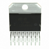
L298N STMicroelectronics, L298N Datasheet

L298N
Specifications of L298N
Available stocks
Related parts for L298N
L298N Summary of contents
Page 1
... BLOCK DIAGRAM Jenuary 2000 DUAL FULL-BRIDGE DRIVER Multiwatt15 ORDERING NUMBERS : L298N (Multiwatt Vert.) L298HN (Multiwatt Horiz.) L298P (PowerSO20) nection of an external sensing resistor. An additional supply input is provided so that the logic works at a lower voltage. ...
Page 2
L298 ABSOLUTE MAXIMUM RATINGS Symbol V Power Supply S V Logic Supply Voltage Input and Enable Voltage Peak Output Current (each Channel) O – Non Repetitive (t = 100 s) –Repetitive (80% on –20% ...
Page 3
PIN FUNCTIONS (refer to the block diagram) MW.15 PowerSO 1;15 2;19 Sense A; Sense B 2;3 4;5 Out 1; Out 5;7 7;9 Input 1; Input 2 6;11 8;14 Enable A; Enable B 8 1,10,11, 10; ...
Page 4
L298 ELECTRICAL CHARACTERISTICS (continued) Symbol Parameter Source Current Turn-off Delay Source Current Fall Time Source Current Turn-on Delay Source Current Rise Time ...
Page 5
Figure 3 : Source Current Delay Times vs. Input or Enable Switching. Figure 4 : Switching Times Test Circuits. Note : For INPUT Switching, set For ENABLE Switching, set L298 5/13 ...
Page 6
L298 Figure 5 : Sink Current Delay Times vs. Input 0 V Enable Switching. Figure 6 : Bidirectional DC Motor Control. 6/13 Inputs ...
Page 7
Figure 7 : For higher currents, outputs can be paralleled. Take care to parallel channel 1 with channel 4 and channel 2 with channel 3. APPLICATION INFORMATION (Refer to the block diagram) 1.1. POWER OUTPUT STAGE The L298 integrates two ...
Page 8
L298 This solution can drive until 3 Amps In DC operation and until 3.5 Amps of a repetitive peak current. On Fig shown the driving of a two phase bipolar stepper motor ; the needed signals to ...
Page 9
Figure 9 : Suggested Printed Circuit Board Layout for the Circuit of fig. 8 (1:1 scale). Figure 10 : Two Phase Bipolar Stepper Motor Control Circuit by Using the Current Controller L6506. R and R depend from the load current ...
Page 10
L298 mm DIM. MIN. TYP. MAX. MIN 2. 0.49 0.55 0.019 F 0.66 0.75 0.026 G 1.02 1.27 1.52 0.040 G1 17.53 17.78 18.03 0.690 H1 19.6 0.772 H2 20.2 L 21.9 ...
Page 11
DIM. MIN. TYP. MAX. MIN 2.65 C 1.6 E 0.49 0.55 0.019 F 0.66 0.75 0.026 G 1.14 1.27 1.4 0.045 G1 17.57 17.78 17.91 0.692 H1 19.6 0.772 H2 20.2 L 20.57 L1 18.03 L2 ...
Page 12
L298 mm DIM. MIN. TYP. MAX. MIN. A 3.6 a1 0.1 0.3 0.004 a2 3 0.1 0.000 b 0.4 0.53 0.016 c 0.23 0.32 0.009 D (1) 15.8 16 0.622 D1 9.4 9.8 0.370 E 13.9 14.5 0.547 ...
Page 13
... No license is granted by implication or otherwise under any patent or patent rights of STMicroelectronics. Specification mentioned in this publication are subject to change without notice. This publication supersedes and replaces all information previously supplied. STMi- croelectronics products are not authorized for use as critical components in life support devices or systems without express written approval of STMicroelectronics ...


