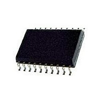
L6201PS STMicroelectronics, L6201PS Datasheet - Page 5

L6201PS
Manufacturer Part Number
L6201PS
Description
IC DRIVER FULL BRIDGE 20-PWRSOIC
Manufacturer
STMicroelectronics
Type
H Bridger
Datasheet
1.L6201013TR.pdf
(20 pages)
Specifications of L6201PS
Input Type
Non-Inverting
Number Of Outputs
2
On-state Resistance
300 mOhm
Current - Output / Channel
4A
Current - Peak Output
5A
Voltage - Supply
12 V ~ 48 V
Operating Temperature
-40°C ~ 150°C
Mounting Type
Surface Mount
Package / Case
PowerSO-20 Exposed Bottom Pad
Operating Supply Voltage
12 V to 48 V
Supply Current
0.015 A
Mounting Style
SMD/SMT
Motor Type
Full Bridge
No. Of Outputs
2
Output Current
5A
Output Voltage
60V
Supply Voltage Range
12V To 48V
Driver Case Style
SOIC
No. Of Pins
20
Operating Temperature Range
-40°C To +150°C
Rohs Compliant
Yes
Operating Current
15mA
Operating Temperature Classification
Automotive
Package Type
PowerSO
Operating Supply Voltage (min)
12V
Operating Supply Voltage (typ)
36V
Operating Supply Voltage (max)
48V
Lead Free Status / RoHS Status
Lead free / RoHS Compliant
Other names
497-1419-5
Available stocks
Company
Part Number
Manufacturer
Quantity
Price
Company:
Part Number:
L6201PS
Manufacturer:
STMicroelectronics
Quantity:
135
Part Number:
L6201PSTR
Manufacturer:
SOIC20
Quantity:
20 000
Company:
Part Number:
L6201PSTR-ST
Manufacturer:
ST
Quantity:
6
ELECTRICAL CHARACTERISTICS (Continued)
LOGIC CONTROL TO POWER DRIVE TIMING
(*) Limited by power dissipation
(**) In synchronous rectification the drain-source voltage drop VDS is shown in fig. 4 (L6202/03); typical value for the L6201 is of 0.3V.
Figure 1: Typical Normalized I
Figure 3: Typical Normalized I
Symbol
t
t
t
t
t
t
t
t
1
2
3
4
5
6
7
8
(V
(V
(V
(V
(V
(V
(V
(V
i
i
i
i
i
i
i
i
)
)
)
)
)
)
)
)
Source Current Turn-off Delay
Source Current Fall Time
Source Current Turn-on Delay
Source Current Rise Time
Sink Current Turn-off Delay
Sink Current Fall Time
Sink Current Turn-on Delay
Sink Current Rise Time
Parameter
S
S
vs. T
vs. V
j
S
Fig. 12
Fig. 12
Fig. 12
Fig. 12
Fig. 13
Fig. 13
Fig. 13
Fig. 13
Test Conditions
Figure 2: Typical Normalized Quiescent Current
Figure 4: Typical R
vs. Frequency
DS (ON)
Min.
L6201 - L6202 - L6203
vs. V
Typ.
300
400
400
200
200
300
200
200
S
~ V
Max.
ref
Unit
ns
ns
ns
ns
ns
ns
ns
ns
5/20


