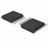
BA6845FS-E2 Rohm Semiconductor, BA6845FS-E2 Datasheet - Page 5

BA6845FS-E2
Manufacturer Part Number
BA6845FS-E2
Description
IC DRIVER STEP MOTOR 1A SSOP-A16
Manufacturer
Rohm Semiconductor
Type
Bipolar Stepper Motor Driverr
Specifications of BA6845FS-E2
Applications
Stepper Motor Driver
Number Of Outputs
1
Current - Output
1A
Voltage - Supply
2.7 V ~ 9 V
Operating Temperature
-25°C ~ 75°C
Mounting Type
Surface Mount
Package / Case
16-SSOP
No. Of Outputs
4
Output Current
1A
Supply Voltage Range
2.7V To 9V
Driver Case Style
SSOP
No. Of Pins
16
Operating Temperature Range
-25°C To +75°C
Svhc
No SVHC (18-Jun-2010)
Operating
RoHS Compliant
Product
Stepper Motor Controllers / Drivers
Operating Supply Voltage
5 V
Supply Current
55 mA
Mounting Style
SMD/SMT
Motor Type
Stepper
Rohs Compliant
Yes
Base Number
684
Lead Free Status / RoHS Status
Lead free / RoHS Compliant
Voltage - Load
-
Lead Free Status / Rohs Status
Lead free / RoHS Compliant
Other names
BA6845FS-E2TR
Available stocks
Company
Part Number
Manufacturer
Quantity
Price
Company:
Part Number:
BA6845FS-E2
Manufacturer:
AD
Quantity:
1 430
Company:
Part Number:
BA6845FS-E2
Manufacturer:
Rohm
Quantity:
2 500
Part Number:
BA6845FS-E2
Manufacturer:
ROHM/罗姆
Quantity:
20 000
FApplication example
FOperation notes
(1)
Do not apply voltage to control logic pins (pins 4, 5, 12,
and 13) when the V
voltage of each pin should be less than V
and should be more than the ground voltage.
(2)
When changing the rotational direction of a motor, a large
current of up to a few hundred milliamperes can flow be-
tween the motor power supply (pins 11 and 14) and
MGND (pins 1 and 8). Depending on the application, this
large output current may flow back to input pins, resulting
in output oscillation or other malfunctions. Make sure that
your design does not allow a common impedance be-
tween the large current output lines and the input section.
Suppress the power supply impedance to low levels,
otherwise output oscillation may occur.
Motor driver ICs
Control logic pins
PCB arrangement
CC
voltage is not applied to the IC. The
CC
, if applied,
(3)
The power dissipated by the IC varies widely with the
supply voltage and the output current. Give full consider-
ation to the package power dissipation rating when set-
ting the supply voltage and the output current.
(4)
Pins 1, 3, 6, and 8 should have the lowest potential
(ground potential) in the IC.
(5)
This circuit shuts down all the driver outputs when the
chip junction temperature is increased to about 175_C
(typical). The thermal shutdown circuit is deactivated
when the temperature drops to about 20_C (typical).
(6)
These pins have characteristics negatively correlated to
temperature. Give full consideration to the temperature
effect when using the IC.
Package power dissipation
Ground pins
Thermal shutdown circuit
Input pins (pins 4, 5, 12, and 13)
BA6845FS
739


