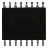
A3953SLBTR-T Allegro Microsystems Inc, A3953SLBTR-T Datasheet - Page 11

A3953SLBTR-T
Manufacturer Part Number
A3953SLBTR-T
Description
IC MOTOR DRIVER PWM FULL 16-SOIC
Manufacturer
Allegro Microsystems Inc
Datasheet
1.A3953SLBTR-T.pdf
(12 pages)
Specifications of A3953SLBTR-T
Applications
PWM Motor Driver
Number Of Outputs
1
Current - Output
±1.3A
Voltage - Load
3 V ~ 50 V
Voltage - Supply
3 V ~ 5.5 V
Operating Temperature
-20°C ~ 85°C
Mounting Type
Surface Mount
Package / Case
16-SOIC (0.300", 7.5mm Width)
Motor Type
Full Bridge
No. Of Outputs
1
Output Current
1.3A
Output Voltage
50V
Supply Voltage Range
3V To 5.5V
Driver Case Style
SOIC
No. Of Pins
16
Lead Free Status / RoHS Status
Lead free / RoHS Compliant
Other names
620-1133-2
A3953SLBTR-T
A3953SLBTR-T
Available stocks
Company
Part Number
Manufacturer
Quantity
Price
Part Number:
A3953SLBTR-T
Manufacturer:
ALLEGRO/雅丽高
Quantity:
20 000
A3953
the need to generate a variable analog voltage reference. In this
case, a dc voltage on the REF input is used typically to limit the
maximum load current.
In dc servo applications, which require accurate positioning
at low or zero speed, PWM of the PHASE input is selected
typically. This simplifies the servo control loop because the
transfer function between the duty cycle on the PHASE input and
the average voltage applied to the motor is more linear than in the
case of ENABLE PWM control (which produces a discontinuous
current at low current levels).
With bidirectional dc servo motors, the PHASE terminal can be
used for mechanical direction control. Similar to when braking
the motor dynamically, abrupt changes in the direction of a
rotating motor produces a current generated by the back-EMF.
The current generated will depend on the mode of operation. If
the internal current control circuitry is not being used, then the
maximum load current generated can be approximated by I
(V
speed. If the internal slow current-decay control circuitry is used,
then the maximum load current generated can be approximated
by I
ensure that the maximum ratings of the device are not exceeded.
If the internal fast current-decay control circuitry is used, then the
BEMF
LOAD
+ V
= V
BB
BEMF
)/R
LOAD
/R
LOAD
where V
. For both cases care must be taken to
BEMF
is proportional to the motor’s
Figure 4 — Typical Application
LOAD
=
load current will regulate to a value given by:
CAUTION
the motor is changed abruptly, the kinetic energy stored in the
motor and load inertia will be converted into current that charges
the V
decoupling capacitance). Care must be taken to ensure that the
capacitance is sufficient to absorb the energy without exceeding
the voltage rating of any devices connected to the motor supply.
See also the Brake Operation section, above.
Soldering Considerations
matte tin) plating on lead terminations is 100% backward-
compatible for use with traditional tin-lead solders of any
composition, at any temperature of soldering that has been
traditionally used for that tin-lead solder alloy. Further, 100%
matte tin finishes solder well with tin-lead solders even at
temperatures below 232°C. This is because the matte tin dissolves
easily in the tin-lead. Additional information on soldering is
available on the Allegro Web site, www.allegromicro.com.
Full-Bridge PWM Motor Driver
BB
supply bulk capacitance (power supply output and
: In fast current-decay mode, when the direction of
I
LOAD
115 Northeast Cutoff
1.508.853.5000; www.allegromicro.com
Allegro MicroSystems, Inc.
Worcester, Massachusetts 01615-0036 U.S.A.
= V
. The lead (Pb) free (100%
REF
/R
S
.
10


