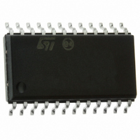
E-L6219DS013TR STMicroelectronics, E-L6219DS013TR Datasheet - Page 7

E-L6219DS013TR
Manufacturer Part Number
E-L6219DS013TR
Description
IC STEPPER MOTOR DRIVER 24-SOIC
Manufacturer
STMicroelectronics
Type
Stepper Motor Controllerr
Datasheet
1.E-L6219DS013TR.pdf
(16 pages)
Specifications of E-L6219DS013TR
Applications
DC Motor Driver, Stepper Motor Driver
Number Of Outputs
2/1
Current - Output
±750mA
Voltage - Load
10 V ~ 46 V
Voltage - Supply
4.75 V ~ 5.25 V
Operating Temperature
-20°C ~ 85°C
Mounting Type
Surface Mount
Package / Case
24-SOIC (7.5mm Width)
Product
Stepper Motor Controllers / Drivers
Operating Supply Voltage
10 V to 46 V
Supply Current
15 mA
Mounting Style
SMD/SMT
Lead Free Status / RoHS Status
Lead free / RoHS Compliant
Other names
497-3647-2
E-L6219DS013TR
L6219DS013TR
E-L6219DS013TR
L6219DS013TR
Available stocks
Company
Part Number
Manufacturer
Quantity
Price
Company:
Part Number:
E-L6219DS013TR
Manufacturer:
ST
Quantity:
9 640
Company:
Part Number:
E-L6219DS013TR
Manufacturer:
STMicroelectronics
Quantity:
6 464
Company:
Part Number:
E-L6219DS013TR
Manufacturer:
STMicroelectronics
Quantity:
190
Part Number:
E-L6219DS013TR
Manufacturer:
ST
Quantity:
20 000
Company:
Part Number:
E-L6219DS013TR(L6219DS013TR)
Manufacturer:
ST-MICROE
Quantity:
1 184
L6219
Note:
Table 3.
ESD on GND, V
model, 1500 W, 100 pF).
Figure 3.
Table 4.
1. With minimized copper area.
Parameter
R
R
thj-case
thj-amb
10, 16
11, 15
12, 14
Pin #
13
24
Thermal resistance junction-case
Thermal resistance junction-ambient
Pin functions (continued)
Timing diagram
Thermal data
S
, V
V
Reference voltage
V
SS
SS
S
- Load supply
- Logic supply Supply voltage input for logic circuitry
, OUT 1 A and OUT 2 A is guaranteed up to 1.5 KV (human body
Phase
Name
RC
Description
This TTL-compatible logic inputs sets the direction of
current flow through the load. A high level causes current to
flow from output A (source) to output B (sink). A schmitt
trigger on this input provides good noise immunity and a
delay circuit prevents output stage short circuits during
switching
A voltage applied to this pin sets the reference voltage of the
comparators, this determining the output current (also thus
depending on Rs and the two inputs input 0 and input 1)
A parallel RC network connected to this pin sets the OFF
time of the higher power transistors. The pulse generator is
a monostable triggered by the output of the comparators
(toff = 1.1 RT CT)
Supply voltage input for the output stages
max.
max.
Description
PDIP
60
14
(1)
75
SO
18
(1)
Block diagram
°C/W
°C/W
Unit
7/16


