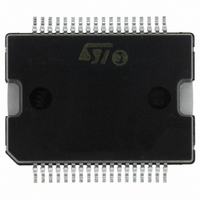
L6229PDTR STMicroelectronics, L6229PDTR Datasheet - Page 14

L6229PDTR
Manufacturer Part Number
L6229PDTR
Description
IC DRIVER 3PH DC MOTOR 36PWRSOIC
Manufacturer
STMicroelectronics
Type
3 Phase Brushless DC Motor Driverr
Datasheet
1.L6229DTR.pdf
(25 pages)
Specifications of L6229PDTR
Applications
DC Motor Driver, Brushless (BLDC), 3 Phase
Number Of Outputs
1
Current - Output
2.8A
Voltage - Supply
12 V ~ 52 V
Operating Temperature
-40°C ~ 150°C
Mounting Type
Surface Mount
Package / Case
36-PowerSOIC
Operating Supply Voltage
8 V to 52 V
Supply Current
1.4 A
Mounting Style
SMD/SMT
For Use With
497-5491 - EVAL BOARD FOR L6229PD SOIC
Lead Free Status / RoHS Status
Lead free / RoHS Compliant
Voltage - Load
-
Lead Free Status / Rohs Status
Lead free / RoHS Compliant
Other names
497-4215-2
Available stocks
Company
Part Number
Manufacturer
Quantity
Price
L6229
Figure 16. 60° Hall Sensor Sequence.
3.6 TACHO
A tachometer function consists of a monostable, with constant off time (t
signal (H
18. For component values refer to Application Information section.
The monostable output drives an open drain output pin (TACHO). At each rising edge of the Hall Effect Sensors
H
t
to the pin RCPULSE. Figure 19 gives the relation between t
where C
By connecting the tachometer pin to an external pull-up resistor, the output signal average value V
tional to the frequency of the Hall Effect signal and, therefore, to the motor speed. This realizes a simple Fre-
quency-to-Voltage Converter. An op amp, configured as an integrator, filters the signal and compares it with a
reference voltage V
Figure 17. Tacho Operation Waveforms.
14/25
PULSE
1
, the monostable is triggered and the MOSFET connected to pin TACHO is turned off for a constant time
= H
t
PULSE
V
(see Figure 17). The off time t
M
H
PUL
1
3
1
). It allows developing an easy speed control loop by using an external op amp, as shown in Figure
=
should be chosen in the range 1nF … 100nF and R
= 0.6 · R
t
----------------- - V
P UL SE
= L
T
H
H
1
2
REF
⋅
PUL
, which sets the speed of the motor.
DD
· C
H
3
2
V
PUL
TACHO
H
H
H
V
M
1
2
3
H
H
1
2
PULSE
can be set using the external RC network (R
H
3b
t
3
PULSE
H
H
V
T
1
2
DD
PULSE
H
3
4
PUL
and C
in the range 20KΩ … 100KΩ.
H
H
1
2
PULSE
PUL
, R
), whose input is one Hall Effect
PUL
H
5
3
. We have approximately:
H
H
PUL
1
2
, C
PUL
H
6b
) connected
M
3
is propor-
H
H
1
2


