L6563HTR STMicroelectronics, L6563HTR Datasheet - Page 24

L6563HTR
Manufacturer Part Number
L6563HTR
Description
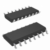
IC PFC CTRLR TRANSITION 16SOIC
Manufacturer
STMicroelectronics
Specifications of L6563HTR
Mode
Discontinuous (Transition)
Current - Startup
90µA
Voltage - Supply
10.3 V ~ 22.5 V
Operating Temperature
-25°C ~ 125°C
Mounting Type
Surface Mount
Package / Case
16-SOIC (3.9mm Width)
For Use With
497-9082 - EVAL BOARD L6563 (200W)497-8850 - BOARD EVAL FOR L6563/STW55NM60N497-8834 - BOARD DEMO FOR L6563/LL6566A
Lead Free Status / RoHS Status
Lead free / RoHS Compliant
Frequency - Switching
-
Lead Free Status / Rohs Status
Lead free / RoHS Compliant
Other names
497-9075-2
Available stocks
Company
Part Number
Manufacturer
Quantity
Price
Company:
Part Number:
L6563HTR
Manufacturer:
ST
Quantity:
3 100
Company:
Part Number:
L6563HTR
Manufacturer:
TI
Quantity:
10 000
Part Number:
L6563HTR
Manufacturer:
ST
Quantity:
20 000
Application information
6
6.1
24/49
Application information
Overvoltage protection
Normally, the voltage control loop keeps the output voltage Vo of the PFC pre-regulator
close to its nominal value, set by the ratio of the resistors R1 and R2 of the output divider. A
pin of the device (PFC_OK) has been dedicated to monitor the output voltage with a
separate resistor divider (R3 high, R4 low, see
the voltage at the pin reaches 2.5 V if the output voltage exceeds a preset value, usually
larger than the maximum Vo that can be expected.
Example: V
51 kΩ.
When this function is triggered, the gate drive activity is immediately stopped until the
voltage on the pin PFC_OK drops below 2.4 V. Notice that R1, R2, R3 and R4 can be
selected without any constraints. The unique criterion is that both dividers have to sink a
current from the output bus which needs to be significantly higher than the bias current of
both INV and PFC_OK pins.
Figure 38. Output voltage setting, OVP and FFP functions: internal block diagram
O
= 400 V, V
OX
= 434 V. Select: R3 = 8.8 MΩ; then: R4 = 8.8 MΩ ·2.5/(434-2.5) =
Doc ID 16047 Rev 3
Figure
38). This divider is selected so that
L6563H


