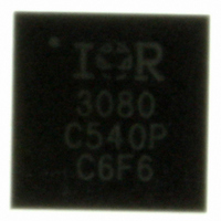
IR3080MTRPBF International Rectifier, IR3080MTRPBF Datasheet - Page 32

IR3080MTRPBF
Manufacturer Part Number
IR3080MTRPBF
Description
IC CONTROLLER PHASE 32LMLPQ
Manufacturer
International Rectifier
Series
XPhase™r
Datasheet
1.IR3080MTRPBF.pdf
(41 pages)
Specifications of IR3080MTRPBF
Applications
Processor
Current - Supply
11mA
Voltage - Supply
9.5 V ~ 14 V
Operating Temperature
0°C ~ 100°C
Mounting Type
Surface Mount
Package / Case
32-MLPQ
Ic Function
Control IC With VCCVID And Overtemp Detect
Supply Voltage Range
9.5V To 14V
Operating Temperature Range
0°C To +100°C
Digital Ic Case Style
MLPQ
No. Of Pins
32
Filter Terminals
SMD
Rohs Compliant
Yes
Controller Type
PWM
Package
32-Lead MLPQ
Circuit
X-Phase Control IC
Switch Freq (khz)
150kHz to 1.0MHz
Pbf
PbF Option Available
Lead Free Status / RoHS Status
Lead free / RoHS Compliant
Other names
IR3080MPBFTR
IR3080MTRPBF
IR3080MTRPBFTR
IR3080MTRPBF
IR3080MTRPBFTR
The power good delay time is
VDAC Slew Rate Programming Capacitor C
From Figure 15, the sink current of VDAC pin corresponding to 800kHz (R
VDAC down-slope slew-rate programming capacitor from the required down-slope slew rate.
Calculate the programming resistor.
From Figure 15, the source current of VDAC pin is 250uA. The VDAC up-slope slew rate is
Over Current Setting Resistor R
The room temperature is 25ºC and the target PCB temperature is 100 ºC. The phase IC die temperature is about 1
ºC higher than that of phase IC, and the inductor temperature is close to PCB temperature.
Calculate Inductor DC resistance at 100 ºC,
The current sense amplifier gain is 34 at 25ºC, and its gain at 101ºC is calculated as,
Set the over current limit at 135A. From Figure 14, the bias current of OCSET pin (I
R
the current sense amplifier input resistor mismatch.
Calculate constant K
No Load Output Voltage Setting Resistor R
From Figure 14, the bias current of FB pin is 90uA with R
t
C
G
R
SR
R
K
R
=
R
VccPG
L
OSC
OCSET
VDAC
VDAC
FB
CS
P
(
UP
_
135
MAX
=
Page 32
_
6
=
MIN
=13.3kΩ. The total current sense amplifier input offset voltage is 0.55mV, which includes the offset created by
=
(
=
V
R
=
=
∗
=
=
I
I
L
C
. 0
0
C
SR
SOURCE
−
[
_
=
5 .
R
SS
VDAC
64
R
I
MAX
V
L
G
SINK
DOWN
LIMIT
+
O
/
_
n
DEL
*
CS
ROOM
)
3
10
∗
∗
2 .
C
_
V
V
I
=
∗
ROOM
−
VDAC
∗
O
*
O
LIMIT
3
=
(
∗
R
I
10
250
_
. 3
/(
∗
68
CHG
1 [
L
I
NLOFST
2
. 1
L
91
FB
−
_
5 .
P,
2
+
*
15
∗
32
∗
/
MAX
170
*
10
*
3850
−
∗
V
10
the ratio of inductor peak current over average current in each phase,
n
1 [
10
=
V
I
R
+
−
−
−
∗
*
L
O
9
∗
0
. 0
−
−
6
1470
_
10
5 .
*
3
f
1 (
V
−
55
MAX
SW
10
=
/
CS
1
+
+
−
10
3
) 3 .
6
−
*
∗
K
_
(
7 .
6
*
10
−
3
68
TOFST
∗
10
) 2
P
6
mV
2 .
=
(
)
−
T
*
OCSET
=
−
*
+
3
=
L
. 0
10
6
* )
10
V
68
_
/
∗
(
15
∗
MAX
12
CS
uS
−
(
30
−
nF
n
9
T
15
*
_
)
−
∗
IC
2 .
10
2
TOFST
−
. 1
R
_
T
=
/(
O
28
−
MAX
ROOM
6
90
1
70
=
)
( *
2 .
]
FB
VDAC
∗
∗
*
. 0
Ω
*
. 3
. 1
−
10
G
)]
10
64
and Adaptive Voltage Positioning Resistor R
91
T
28
CS
=
−
ROOM
−
*
6
−
6
0
/(
_
and Resistor R
10
)
5 .
100
MIN
. 1
=
−
*
135
28
3
)]
. 6
10
*
∗
/
OSC
34
−
=
10
I
−
20
6 /
3
OCSET
. 1
34
90
k
∗
−
*
) 3
Ω
9
=13.3kΩ.
1 [
10
∗
*
∗
+
10
1 [
=
12
−
3850
3
−
. 2
−
∗
−
6
1470
85
800
*
. 0
VDAC
*
. 0
ms
55
10
64
*
*
*
−
10
10
6
10
*
∗
10
3
−
(
−
∗
6
100
3
−
) 2
∗
∗
3
OSC
(
6
101
−
=
∗
25
. 0
=13.3kΩ) is 170uA. Calculate the
. 0
−
)]
32
91
25
=
*
. 0
)]
10
64
=
−
3
m
30
Ω
=
2 .
162
IR3080PbF
OCSET
Ω
DRP
) is 90uA with


