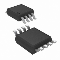
LM5080MM/NOPB National Semiconductor, LM5080MM/NOPB Datasheet - Page 11

LM5080MM/NOPB
Manufacturer Part Number
LM5080MM/NOPB
Description
IC CONTROLLER LOAD SHARE 8-MSOP
Manufacturer
National Semiconductor
Datasheet
1.LM5080MMNOPB.pdf
(13 pages)
Specifications of LM5080MM/NOPB
Applications
Power Supplies, Converters, Controllers
Current - Supply
3.7mA
Voltage - Supply
3 V ~ 14 V
Operating Temperature
-40°C ~ 125°C
Mounting Type
Surface Mount
Package / Case
8-MSOP, Micro8™, 8-uMAX, 8-uSOP,
Lead Free Status / RoHS Status
Lead free / RoHS Compliant
Other names
LM5080MM
LM5080MMTR
LM5080MMTR
Available stocks
Company
Part Number
Manufacturer
Quantity
Price
Part Number:
LM5080MM/NOPB
Manufacturer:
TI/德州仪器
Quantity:
20 000
Voltage Margining
Shifting the output regulation voltage up or down by a small
amount is referred to as voltage margining. In the remote
sense adjust modes and the feedback adjust modes, this
can be done by connecting all of the power converter TRIM
pins together and injecting a positive or negative current.
However, in the reference adjust mode, the TRIM pin is used
for current sharing. An alternative margining method is to
inject a current into the SHR share bus. This will simulta-
neously shift the regulation voltages of all power converter’s
while maintaining equal current sharing. The injected current
is split equally between the LM5080’s SHR inputs and added
to the TRIM pin currents creating an equal offset voltage for
all of the power converter references. The trim pin current
injected into each power converter’s reference (IT) is depen-
dent on the magnitude of the total injected current into the
SHR bus (ISHR), the number of LM5080’s on the SHR bus
(N) and any transconductance boost supplied (R1 & R2):
FIGURE 6. One Method of Implementing Voltage Margining
11
An alternate method to shift the regulation voltage is to tie all
the CSP pins together and inject a current into that node.
The trim pin current injected into each power converter’s
reference (IT) attributed to the current injected into the CSP
node (ICSP) is derived to be:
Figure 6 shows a margining up and down application imple-
mented using pull up resistors to VCC. Since the SHR and
CSP voltages are approximately 0.1 x VCC and 0.2 x VCC
respectively, the injected current can be independently con-
trolled with RM1 and RM2.
20157812
www.national.com


