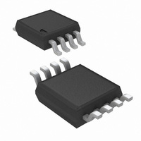
LM5080MM/NOPB National Semiconductor, LM5080MM/NOPB Datasheet - Page 12

LM5080MM/NOPB
Manufacturer Part Number
LM5080MM/NOPB
Description
IC CONTROLLER LOAD SHARE 8-MSOP
Manufacturer
National Semiconductor
Datasheet
1.LM5080MMNOPB.pdf
(13 pages)
Specifications of LM5080MM/NOPB
Applications
Power Supplies, Converters, Controllers
Current - Supply
3.7mA
Voltage - Supply
3 V ~ 14 V
Operating Temperature
-40°C ~ 125°C
Mounting Type
Surface Mount
Package / Case
8-MSOP, Micro8™, 8-uMAX, 8-uSOP,
Lead Free Status / RoHS Status
Lead free / RoHS Compliant
Other names
LM5080MM
LM5080MMTR
LM5080MMTR
Available stocks
Company
Part Number
Manufacturer
Quantity
Price
Part Number:
LM5080MM/NOPB
Manufacturer:
TI/德州仪器
Quantity:
20 000
www.national.com
General Design Procedure
1. Select an appropriate sense resistor value. More sense
2. For the reference adjust and feedback adjust modes,
3. Compensate the current share loop by selecting an
voltage will result in better load sharing but more effi-
ciency loss. Sense voltages of 50mV or more are rec-
ommended. In addition, the sense voltage at full load
should be less than 5% of VCC in applications that
control the remote sense terminals of the power supply.
determine if transconductance (gm) boosting is required.
Boosting the transconductance also boosts the TRO pin
current limit. The TRO pin current limit (approximately
10µA typical) multiplied by the reference impedance de-
termines the maximum correction the LM5080 can make
to the reference. The LM5080 must have enough TRO
current to adjust the converter output voltage by at least
the accuracy of the reference. For example, if the refer-
ence accuracy is
to adjust the reference by at least 2% (in the event one
converter is 2% high and the other 2% low).
appropriate capacitance for CTRO. The compensation
±
2%, the LM5080 must have the ability
12
4. If RTRO
of the current share loop is dependent on the frequency
response of the output voltage to the controlling node of
the converter (TRIM pin, feedback divider or remote
sense pins). Given the wide variety of converter designs
and the many operating modes of the LM5080, selection
of CTRO is best accomplished using a simple iterative
procedure. Start with a large capacitance in TRO (100µF
or more). While monitoring the load current in each
converter with a current probe, determine the minimum
CTRO required for stability by decreasing CTRO until
the current sharing becomes unstable under step loads.
The step loads should be more than 50% of the load
range and applied at a frequency well below the cross
over frequency of the converter. The TRO capacitance
can be further reduced by introducing some resistance
(RTRO) in series with CTRO to cancel the 2nd order
poles within the converter.
second CTRO capacitor ( ~ 2nF) should be added be-
tween TRO and CSP to keep the error amplifier stable.
>
100 Ω in either remote sense mode, a


