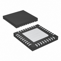
MAX8798ETX+ Maxim Integrated Products, MAX8798ETX+ Datasheet - Page 19

MAX8798ETX+
Manufacturer Part Number
MAX8798ETX+
Description
IC INTERNAL-SW BOOST REG 36-TQFN
Manufacturer
Maxim Integrated Products
Datasheet
1.MAX8798ETX.pdf
(31 pages)
Specifications of MAX8798ETX+
Applications
LCD Monitor, Notebook Display
Current - Supply
400µA
Voltage - Supply
1.8 V ~ 6 V
Operating Temperature
-40°C ~ 85°C
Mounting Type
Surface Mount
Package / Case
36-TQFN Exposed Pad
Operating Supply Voltage
1.8 V to 5.5 V
Maximum Operating Temperature
- 40 C
Mounting Style
SMD/SMT
Maximum Power Dissipation
2179.8 mW
Minimum Operating Temperature
+ 85 C
Supply Current
4 uA
Input Voltage
4V
Output Current
400mA
Output Voltage
18V
No. Of Outputs
2
Power Dissipation Pd
2.18W
Supply Voltage Range
1.8V To 5.5V
No. Of Pins
36
Operating Temperature Range
-40°C To +85°C
Rohs Compliant
Yes
Lead Free Status / RoHS Status
Lead free / RoHS Compliant
The MAX8798 includes an internal 3.3V linear regulator.
BOOST is the input of the linear regulator. The input volt-
age range is between 5V and 18V. The regulator powers
all the internal circuitry including the MOSFET gate dri-
ver. Bypass VL to AGND with a 0.22µF or greater ceram-
ic capacitor. Connect BOOST directly to the output of the
step-up regulator. This feature significantly improves the
efficiency at low input voltages.
The MAX8798 features bootstrapping operation. In nor-
mal operation, the internal linear regulator supplies
power to the internal circuitry. Connect the input of the
linear regulator (BOOST) directly to the output of the
step-up regulator. The MAX8798 is enabled when the
voltages at IN and BOOST are above their UVLO
thresholds and the fault latch is not set. After being
enabled, the regulator starts open-loop switching to
generate the supply voltage for the linear regulator. The
internal reference block turns on when the VL voltage
exceeds its 2.7V (typ). When the reference voltage
reaches regulation, the PWM controller and the current-
limit circuit are enabled and the step-up regulator
enters soft-start. During soft-start, the main step-up reg-
ulator directly limits the peak inductor current, allowing
from zero up to the full current-limit value in 128 equal
current steps. The maximum load current is available
after the output voltage reaches regulation (that termi-
nates soft-start), or after the soft-start timer expires in
approximately 3ms. The soft-start routine minimizes
inrush current and voltage overshoot and ensures a
well-defined startup behavior.
During steady-state operation, the MAX8798 monitors
the FB voltage. If the FB voltage does not exceed 1V
(typ), the MAX8798 activates an internal fault timer. If
there is a continuous fault for the fault-timer duration,
the MAX8798 sets the fault latch, turning off the main
step-up regulator and the linear regulator, disabling the
switch-control block and the operational amplifier.
Once the fault condition is removed, cycle the input
voltage to clear the fault latch and reactivate the
device. The fault-detection circuit is disabled during the
soft-start time.
Integrated 3-Channel Scan Driver for TFT LCDs
______________________________________________________________________________________
Bootstrapping and Soft-Start
Internal-Switch Boost Regulator with
Linear Regulator (VL)
Fault Protection
The MAX8798 monitors BOOST for undervoltage and
overvoltage conditions. If the BOOST voltage is below
1.4V (typ) or above 19V (typ), the MAX8798 disables the
gate driver of the step-up regulator and prevents the
internal MOSFET from switching. The BOOST undervolt-
age and overvoltage conditions do not set the fault latch.
The MAX8798 has an operational amplifier that is typi-
cally used to drive the LCD backplane (VCOM) or the
gamma-correction-divider string. The operational
amplifier features ±150mA output short-circuit current,
40V/µs slew rate, and 20MHz bandwidth. While the op
amp is a rail-to-rail input and output design, its accura-
cy is significantly degraded for input voltages within 1V
of its supply rails (BOOST and BGND).
The operational amplifier limits short-circuit current to
approximately ±150mA if the output is directly shorted to
BOOST or to AGND. If the short-circuit condition per-
sists, the junction temperature of the IC rises until it
reaches the thermal-shutdown threshold (+160°C typ).
Once the junction temperature reaches the thermal-shut-
down threshold, an internal thermal sensor immediately
sets the thermal-fault latch, shutting off the main step-up
regulator, the linear regulator, the switch-control block,
and the operational amplifier. Those portions of the
device remain inactive until the input voltage is cycled.
The operational amplifier is typically used to drive the
LCD backplane (VCOM) or the gamma-correction-
divider string. The LCD backplane consists of a distrib-
uted series capacitance and resistance, a load that can
be easily driven by the operational amplifier. However,
if the operational amplifier is used in an application with
a pure capacitive load, steps must be taken to ensure
stable operation.
As the operational amplifier’s capacitive load increases,
the amplifier’s bandwidth decreases and gain peaking
increases. A 5Ω to 50Ω small resistor placed between
VCOM and the capacitive load reduces peaking, but
also reduces the gain. An alternative method of reducing
peaking is to place a series RC network (snubber) in par-
allel with the capacitive load. The RC network does not
continuously load the output or reduce the gain. Typical
values of the resistor are between 100Ω and 200Ω and
the typical value of the capacitor is 10pF.
Driving Pure Capacitive Loads
Short-Circuit Current Limit
Operational Amplifier
19


