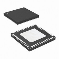
ISL6595DRZ-T Intersil, ISL6595DRZ-T Datasheet - Page 9

ISL6595DRZ-T
Manufacturer Part Number
ISL6595DRZ-T
Description
IC DIGITL MULTIPHASE CTRLR 48QFN
Manufacturer
Intersil
Datasheet
1.ISL6595DRZ-T.pdf
(22 pages)
Specifications of ISL6595DRZ-T
Applications
Digital Multiphase Controller
Voltage - Supply
3 V ~ 3.6 V
Current - Supply
100mA
Operating Temperature
0°C ~ 85°C
Mounting Type
Surface Mount
Package / Case
48-VQFN
Lead Free Status / RoHS Status
Lead free / RoHS Compliant
Voltage - Input
-
Pin Description
General Description
The ISL6595 is a digital multiphase pulse width modulation
controller integrated circuit for use in 2-phase to 6-phase
synchronous buck converter CPU core supply power
switching regulators. The device is optimized for delivering
voltages from 0.5V to 1.6V at high current levels (120A+)
with programmable PWM switching frequencies between
100kHz and 2MHz. The ISL6595 brings the benefit of digital
control to voltage regulators targeting Intel™ VRD/VRM 10.x,
11.0 and similar applications.
The ISL6595 is designed to maximize value to the user by
providing features, monitoring and performance to minimize
the number of required off-chip components, work with a
variety of widely available standard components, and to
accommodate wider device tolerance mismatches than
competing analog controller solutions.
The ISL6595 provides both ease-of-use and flexibility to the
user. Major features include:
• Internal Voltage and Temperature Reference – An
PIN #
internal factory trimmed ±0.5% voltage reference sets the
VID DAC, voltage ADC and current ADC range. In
addition, a proportional-to-absolute-temperature (PTAT)
34
35
36
37
38
39
40
41
42
43
44
45
46
47
48
ISEN2-
ISEN2+
VDD
PWM2
ISEN1-
ISEN1+
PWM1
CAL_CUR_SEN
CAL_CUR_EN
LL0
RESET_N
SADDR
SDA
SCL
VDD25
NAME
(Continued)
9
I/O
O
O
O
I
I
I
I
I
I
I
I
I
I
I
I
Analog
VDD
3.3V CMOS
Analog
3.3V CMOS
Analog
Analog
1.2V CMOS
3.3V CMOS
3.3V CMOS
3.3V CMOS
3.3V CMOS
Analog
TYPE
Phase channel #2 ADC current sense (-) input, tie to ground if the phase is unused.
Phase channel #2 ADC current sense (+) input.
3.3V power supply connection, decoupling cap should be placed close to pin.
Phase channel #2 PWM output.
Phase channel #1 ADC current sense (-) input, tie to ground if the phase is unused.
Phase channel #1 ADC current sense (+) input.
Phase channel #1 PWM output.
Calibration current sense input. Measures the voltage across the calibration sense
resistor and adjusts CAL_CUR_EN via an op amp loop such that the voltage across the
resistor is 200mV.
Calibration current enable output. Drives the calibration FET gate voltage to adjust its
r
Processor load line select input control signal (LSB). Selects regulator load line
resistance and loadline offset voltage.
Active LOW asynchronous system reset to place ISL6595 into default state.
“1”
“0”
I
“1”
“0”
I
I
Decoupling capacitor for 2.5V internally generated voltage, recommend
0.01µF, 0.1µF max.
DS(ON)
2
2
2
C address LSB select.
C interface serial data line.
C interface serial clock line.
asynchronous reset disabled
Address 1110001 selected
Address 1110000 selected
asynchronous reset enabled
ISL6595
such that voltage across the sense resistor is set at 200mV.
• Internal Oscillator – Provides a factory trimmed
• Dedicated Voltage ADC – A high precision differential
• Multiplexed Current Sense ADC – The average currents
reference is generated and digitized to serve as the
controller temperature sensor.
156.25MHz ±10% clock reference. Fixed and
programmable dividers generate all the needed internal
clocks to configure the controller’s switching frequency
and number of active phases.
input voltage ADC digitizes the differential remote sense
voltage. An integrated anti-alias filter and ripple frequency
null filter minimize the impact of high frequency noise on
the system.
from each phase are sensed as a voltage across the low
side FET using the multiplexed current ADC. Each phase
is sampled at the middle of its cycle, with timing optimized
through a programmable delay line. The internal
temperature reference and external thermistor
temperature are also digitized using the multiplexed
current ADC. Gain and offset of the sensor and ADC are
compensated through either a one time factory calibration,
or through a power-up calibration each time the output
voltage is reset.
DESCRIPTION
December 4, 2008
FN9192.2


