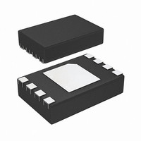
STTS2002B2DN3F STMicroelectronics, STTS2002B2DN3F Datasheet - Page 19

STTS2002B2DN3F
Manufacturer Part Number
STTS2002B2DN3F
Description
IC MEMORY MOD TEMP SENSOR 8-TDF
Manufacturer
STMicroelectronics
Specifications of STTS2002B2DN3F
Function
Temp Monitoring System (Sensor)
Topology
ADC (Sigma Delta), EEPROM, Register Bank
Sensor Type
Internal
Sensing Temperature
-40°C ~ 125°C
Output Type
I²C™/SMBus™
Output Alarm
Yes
Output Fan
No
Voltage - Supply
2.3 V ~ 3.6 V
Operating Temperature
-40°C ~ 125°C
Mounting Type
Surface Mount
Package / Case
8-TDFN
Lead Free Status / RoHS Status
Lead free / RoHS Compliant
Other names
497-10634-2
Available stocks
Company
Part Number
Manufacturer
Quantity
Price
STTS424E02
4.2
4.2.1
4.2.2
4.2.3
4.2.4
Note:
Configuration register (read/write)
The 16-bit configuration register stores various configuration modes that are used to set up
the sensor registers and configure according to application and JEDEC requirements (see
Table 8 on page 19
Event thresholds
All event thresholds use hysteresis as programmed in register address 0x01 (bits 10 through
9) to be set when they de-assert.
Interrupt mode
The interrupt mode allows an event to occur where software may write a '1' to the clear
event bit (bit 5) to de-assert the event interrupt output until the next trigger condition occurs.
Comparator mode
Comparator mode enables the device to be used as a thermostat. READs and WRITEs on
the device registers will not affect the event output in comparator mode. The event signal will
remain asserted until temperature drops outside the range or is re-programmed to make the
current temperature “out of range”.
Shutdown mode
The STTS424E02 features a shutdown mode which disables all power-consuming activities
(e.g. temperature sampling operations), and leaves the serial interface active. This is
selected by setting shutdown bit (bit 8) to '1'. In this mode, the devices consume the
minimum current (I
Bit 8 cannot be set to '1' while bits 6 and 7 (the lock bits) are set to '1'.
The device may be enabled for continuous operation by clearing bit 8 to '0'. In shutdown
mode, all registers may be read or written to. Power recycling will also clear this bit and
return the device to continuous mode as well.
Table 8.
Critical
lock bit
Bit15
RFU
Bit7
Alarm lock
Configuration register format
Bit14
RFU
Bit6
bit
SHDN
and
), as shown in
Table 9 on page
Bit13
Clear
event
RFU
Bit5
Doc ID 13448 Rev 8
Event output
status
Bit12
RFU
Bit4
Table 27 on page
20).
Event output
control
Bit11
RFU
Bit3
38.
Temperature sensor registers
Hysteresis Hysteresis
event only
Critical
Bit10
Bit2
polarity
Event
Bit9
Bit1
Shutdown
mode
Event
mode
Bit8
Bit0
19/50


