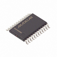
DS1780E Maxim Integrated Products, DS1780E Datasheet - Page 15

DS1780E
Manufacturer Part Number
DS1780E
Description
IC CPU PERIPHERAL MON 24-TSSOP
Manufacturer
Maxim Integrated Products
Datasheet
1.DS1780E.pdf
(28 pages)
Specifications of DS1780E
Function
Thermal Monitor, CPU Peripherals
Topology
ADC (Sigma Delta), Comparator, Fan Speed Control, Register Bank
Sensor Type
Internal
Sensing Temperature
-40°C ~ 125°C
Output Type
I²C™/SMBus™
Output Alarm
No
Output Fan
Yes
Voltage - Supply
2.8 V ~ 5.75 V
Operating Temperature
-40°C ~ 125°C
Mounting Type
Surface Mount
Package / Case
24-TSSOP
Full Temp Accuracy
+/- 12 %
Digital Output - Bus Interface
Serial (2-Wire)
Digital Output - Number Of Bits
8 bit
Maximum Operating Temperature
+ 125 C
Minimum Operating Temperature
- 40 C
Lead Free Status / RoHS Status
Contains lead / RoHS non-compliant
Available stocks
Company
Part Number
Manufacturer
Quantity
Price
Company:
Part Number:
DS1780E
Manufacturer:
MAX
Quantity:
3 000
Part Number:
DS1780E
Manufacturer:
DALLAS
Quantity:
20 000
Part Number:
DS1780E+T&R
Manufacturer:
MAXIM/美信
Quantity:
20 000
Company:
Part Number:
DS1780E+TR
Manufacturer:
MAXIM
Quantity:
1 001
Company:
Part Number:
DS1780E-TR
Manufacturer:
ICS
Quantity:
933
Company:
Part Number:
DS1780E/TR
Manufacturer:
XILINX
Quantity:
17
OPERATION - Analog Output
The DS1780 has a single analog output from a unsigned 8-bit D/A which produces 0-1.25 volts; this is
amplified and scaled with external circuitry such as a op-amp and transistor to provide fan speed control.
This register is set to 0xFF on power-up, which produces full fan speed. The analog output register (19h)
is unaffected by any reset other than power-on.
This voltage must be scaled and have an output current of at least 250 mA which is needed to drive the
fans; Figure 6 is a simple circuit that can be used, and Table 9 suggest R1 and R2 to select gain.
Although it is recommended to connect the DS1780 analog output to a high impedance node such as that
in Figure 6, the output driver can source 2.0 mA (max) at V
of 5% of FSR over temperature and supply voltage. Stability is guaranteed for a load capacitance up to
100 pF. More capacitance could cause severe overshoots and possible oscillation.
FAN AMPLIFIER CIRCUIT EXAMPLE Figure 6
AMPLIFIER DESIGN EXAMPLES Table 9
OPERATION - NAND TREE Test
A NAND tree is provided in the DS1780 for Automated Test Equipment (ATE) board level connectivity
testing. If the user applies (V
A0/NT
NAND tree (see Figure 7 below) should be driven high.
Beginning with A1 and working around the chip, each pin can be toggled and a resulting toggle can be
observed on A0/NT
Allow for a typical propagation delay of 100 ns.
Input
Output
Gain
OUT
will become the NAND tree output pin. To perform a NAND tree test all pins included in the
OUT
.
10,000
1,000
2,200
3,300
4,700
R1
DD
- 0.5V) to the NT
15 of 28
IN
input, the device will be in the NAND tree test mode.
1.22
12
9.84
OUT
= 1.25V while maintaining the error spec
19,439
29,159
41,530
88,361
9,000
R2


