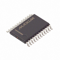
DS1780E Maxim Integrated Products, DS1780E Datasheet - Page 6

DS1780E
Manufacturer Part Number
DS1780E
Description
IC CPU PERIPHERAL MON 24-TSSOP
Manufacturer
Maxim Integrated Products
Datasheet
1.DS1780E.pdf
(28 pages)
Specifications of DS1780E
Function
Thermal Monitor, CPU Peripherals
Topology
ADC (Sigma Delta), Comparator, Fan Speed Control, Register Bank
Sensor Type
Internal
Sensing Temperature
-40°C ~ 125°C
Output Type
I²C™/SMBus™
Output Alarm
No
Output Fan
Yes
Voltage - Supply
2.8 V ~ 5.75 V
Operating Temperature
-40°C ~ 125°C
Mounting Type
Surface Mount
Package / Case
24-TSSOP
Full Temp Accuracy
+/- 12 %
Digital Output - Bus Interface
Serial (2-Wire)
Digital Output - Number Of Bits
8 bit
Maximum Operating Temperature
+ 125 C
Minimum Operating Temperature
- 40 C
Lead Free Status / RoHS Status
Contains lead / RoHS non-compliant
Available stocks
Company
Part Number
Manufacturer
Quantity
Price
Company:
Part Number:
DS1780E
Manufacturer:
MAX
Quantity:
3 000
Part Number:
DS1780E
Manufacturer:
DALLAS
Quantity:
20 000
Part Number:
DS1780E+T&R
Manufacturer:
MAXIM/美信
Quantity:
20 000
Company:
Part Number:
DS1780E+TR
Manufacturer:
MAXIM
Quantity:
1 001
Company:
Part Number:
DS1780E-TR
Manufacturer:
ICS
Quantity:
933
Company:
Part Number:
DS1780E/TR
Manufacturer:
XILINX
Quantity:
17
DS1780
2-WIRE SERIAL COMMUNICATION WITH THE DS1780 Figure 2
OPERATION - Power-on
Applying power to the DS1780 causes a reset of several of the registers. Power-on conditions of the
registers are shown in Table 2 above. Some registers have indeterminate power-on values, such as the
Limit and RAM registers of the Value RAM page, and these are not shown in the table. Upon power-up
the ADC is inactive. Writing Limits into the Value RAM should usually be the first action performed
after power up. The
pin is bi-directional. It forces RESET at power-on, but can also be pulled low to
RST
force RESET internally.
OPERATION - Resets
The DS1780 features four distinct resetting functions. Each one has a different effect on register contents
and the state of the
output following the event. Each one is explained below:
RST
Power-on Reset - On POR, all internal logic is reset, and registers are cleared to their default state (see
tables 10.x). Because Value RAM is typically the first area programmed upon power-up, it does not have
a defined state upon POR. Also, on POR, the
output will be pulled to an active low state for 20 ms
RST
(minimum).
A POR occurs every time V
crosses the voltage level approximately equivalent to the sum of one n-
DD
channel threshold (V
) and one p-channel threshold (V
), on a power-up or power-down condition.
TN
TP
DS1780 SRAM contents get “scrambled” when V
falls below the greater of one n-channel V
or one p-
DD
T
channel V
. Therefore, SRAM contents will always be in a defined state as supply voltage reaches the
T
minimum spec level of 2.8V, even in a power supply brownout condition.
6 of 28


