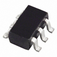
ADR127AUJZ-R2 Analog Devices Inc, ADR127AUJZ-R2 Datasheet - Page 16

ADR127AUJZ-R2
Manufacturer Part Number
ADR127AUJZ-R2
Description
IC V-REF PREC 1.25V TSOT-23-6
Manufacturer
Analog Devices Inc
Datasheet
1.ADR127AUJZ-REEL7.pdf
(20 pages)
Specifications of ADR127AUJZ-R2
Temperature Coefficient
25ppm/°C
Design Resources
Generating a Negative Precision Voltage Reference Without Precision Resistors (CN0005) Single Supply Low Noise LED Current Source Driver Using a Current Output DAC in the Reverse Mode (CN0139)
Reference Type
Series
Voltage - Output
1.25V
Tolerance
±0.24%
Voltage - Input
2.7 ~ 18 V
Number Of Channels
1
Current - Quiescent
95µA
Current - Output
5mA
Operating Temperature
-40°C ~ 125°C
Mounting Type
Surface Mount
Package / Case
TSOT-23-6, TSOT-6
Topology
Series
Input Voltage
2.7V To 18V
Reference Voltage
1.25V
Reference Voltage Tolerance
3mV
Voltage Reference Case Style
TSOT
No. Of Pins
6
Lead Free Status / RoHS Status
Lead free / RoHS Compliant
Current - Cathode
-
Lead Free Status / RoHS Status
Lead free / RoHS Compliant, Lead free / RoHS Compliant
ADR121/ADR125/ADR127
THEORY OF OPERATION
The ADR12x band gap references are the high performance
solution for low supply voltage and low power applications.
The uniqueness of these products lies in their architecture.
POWER DISSIPATION CONSIDERATIONS
The ADR12x family is capable of delivering load currents up to
5 mA with an input range from 3.0 V to 18 V. When this device
is used in applications with large input voltages, care must be
taken to avoid exceeding the specified maximum power
dissipation or junction temperature because this could result
in premature device failure.
Use the following formula to calculate a device’s maximum
junction temperature or dissipation:
where:
T
T
P
θ
JA
D
J
A
is the junction temperature.
is the device power dissipation.
is the ambient temperature.
is the device package thermal resistance.
P
D
=
T
J
θ
−
JA
T
A
Rev. B | Page 16 of 20
(4)
INPUT CAPACITOR
Input capacitors are not required on the ADR12x. There is no
limit for the value of the capacitor used on the input, but a 1 μF
to 10 μF capacitor on the input may improve transient response
in applications where there is a sudden supply change. An
additional 0.1 μF capacitor in parallel also helps reduce noise
from the supply.
OUTPUT CAPACITOR
The ADR12x requires a small 0.1 μF capacitor for stability.
Additional 0.1 μF to 10 μF capacitance in parallel can improve
load transient response. This acts as a source of stored energy
for a sudden increase in load current. The only parameter
affected with the additional capacitance is turn-on time.


