ISL6341ACRZ Intersil, ISL6341ACRZ Datasheet
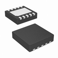
IC CTRLR SYNC BUCK PWM 10-TDFN

ISL6341ACRZ

Manufacturer Part Number
ISL6341ACRZ
Description
IC CTRLR SYNC BUCK PWM 10-TDFN
Manufacturer
Intersil
Datasheet

Specifications of ISL6341ACRZ

Pwm Type
Voltage Mode
Number Of Outputs
1
Frequency - Max
660kHz
Duty Cycle
75%
Voltage - Supply
4.5 V ~ 14.4 V
Buck
Yes
Boost
No
Flyback
No
Inverting
No
Doubler
No
Divider
No
Cuk
No
Isolated
No
Operating Temperature
0°C ~ 70°C
Package / Case
10-TDFN Exposed Pad
Frequency-max
660kHz
Lead Free Status / RoHS Status
Lead free / RoHS Compliant

Available stocks

Company
Part Number
Manufacturer
Quantity
Price
Part Number:
ISL6341ACRZ
Manufacturer:
INTERSIL
Quantity:
20 000
Company:
Part Number:
ISL6341ACRZ
Quantity:
290
5V or 12V Single Synchronous Buck
Pulse-Width Modulation (PWM) Controller
The ISL6341, ISL6341A, ISL6341B, ISL6341C makes
simple work out of implementing a complete control and
protection scheme for a DC/DC stepdown converter driving
N-Channel MOSFETs in a synchronous buck topology. Since
it can work with either 5V or 12V supplies, this one family of
IC’s can be used in a wide variety of applications within a
system. It integrates the control, gate drivers, output
adjustment, monitoring and protection functions into a single
10 Ld Thin DFN package.
The ISL6341, ISL6341A, ISL6341B, ISL6341C (hereafter
referred to as “ISL6341x”, except as needed) provides single
feedback loop, voltage-mode control with fast transient
response. The output voltage can be precisely regulated to as
low as 0.8V, with a maximum tolerance of ±0.8%
over-temperature and line voltage variations. A fixed frequency
oscillator and wide duty cycle range reduces design complexity,
while balancing typical application cost and efficiency. The
frequency, duty cycle and OCP response are the only
differences among the ISL6341x
Protection from overcurrent conditions is provided by
monitoring the r
operation appropriately (see “Overcurrent Protection (OCP)”
on page 8 for details). This approach simplifies the
implementation and improves efficiency by eliminating the
need for a current sense resistor. The output voltage is also
monitored for undervoltage and overvoltage protection, in
addition to monitoring for a PGOOD output.
Ordering Information
ISL6341ACRZ*
ISL6341BCRZ*
ISL6341CCRZ*
ISL6341CRZ*
ISL6341AIRZ*
ISL6341BIRZ*
ISL6341CIRZ*
ISL6341IRZ*
ISL6341EVAL1Z Evaluation Board
*Add “-T” suffix for tape and reel. Please refer to TB347 for details on reel
specifications.
NOTE: These Intersil Pb-free plastic packaged products employ special
Pb-free material sets, molding compounds/die attach materials, and
100% matte tin plate plus anneal (e3 termination finish, which is RoHS
compliant and compatible with both SnPb and Pb-free soldering
operations). Intersil Pb-free products are MSL classified at Pb-free peak
reflow temperatures that meet or exceed the Pb-free requirements of
IPC/JEDEC J STD-020.
PART NUMBER
(Note)
DS(ON)
MARKING
41AC
41BC
41CC
341C
41AI
41BI
41CI
6341
PART
of the lower MOSFET to inhibit PWM
®
RANGE (°C)
-40 to +85
-40 to +85
-40 to +85
-40 to +85
0 to +70
0 to +70
0 to +70
0 to +70
1
TEMP.
versions.
Data Sheet
10 Ld 3x3 TDFN L10.3x3B
See Table 1.
PACKAGE
(Pb-free)
ISL6341, ISL6341A, ISL6341B, ISL6341C
1-888-INTERSIL or 1-888-468-3774
DWG. #
PKG.
CAUTION: These devices are sensitive to electrostatic discharge; follow proper IC Handling Procedures.
Features
• Operates from +4.5V to 14.4V Supply Voltage (for Bias)
• Simple Single-Loop Control Design
• Fast Transient Response
• Lossless, Programmable Overcurrent Protection
• Output Voltage Monitoring
• Small Converter Size in 10 Ld 3x3 Thin DFN
• Pb-Free (RoHS Compliant)
Applications
• Power Supplies for Microprocessors or Peripherals
• Subsystem Power Supplies
• Cable Modems, Set-Top Boxes, and DSL Modems
• Industrial Power Supplies; General Purpose Supplies
• 5V or 12V-Input DC/DC Regulators
• Low-Voltage Distributed Power Supplies; Point of Load
- 1.5V to 12V V
- 0.8V to ~V
- Integrated Gate Drivers; LGATE Uses V
- 0.8V Internal Reference; ±0.8% Tolerance
- Traditional Dual Edge Modulator
- Voltage-Mode PWM Control
- Drives N-Channel MOSFETs
- High-Bandwidth Error Amplifier
- 0% to 85% Max Duty Cycle for ISL6341, ISL6341C
- 0% to 75% Max Duty Cycle for ISL6341A, ISL6341B
- Uses Lower MOSFET’s r
- Latch off mode (ISL6341, ISL6341B)
- Infinite Retry (Hiccup) Mode (ISL6341A)
- Infinite Retry (Hiccup) Mode; no UVP (ISL6341C)
- Undervoltage and Overvoltage Shutdown
- PGOOD Output
- 300kHz Fixed Oscillator (ISL6341, ISL6341C)
- 600kHz Fixed Oscillator (ISL6341A, ISL6341B)
- Fixed Internal Soft-Start, Capable into a Pre-biased
- Enable/Shutdown Function on COMP/EN Pin
- PCs, Servers, Memory Supplies
- DSP and Core Communications Processor Supplies
- PCI, AGP; Graphics Cards; Digital TV
- SSTL-2 and DDR/DDR2/DDR3 SDRAM Bus
December 2, 2008
Restrictions; see “Input Voltage Considerations” on
page 12)
UGATE Uses External Boot Diode to (5V to 12V)
Load
Termination Supply
All other trademarks mentioned are the property of their respective owners.
|
Intersil (and design) is a registered trademark of Intersil Americas Inc.
Copyright © Intersil Americas Inc. 2007, 2008. All Rights Reserved
IN
Output Range (Duty Cycle Limited)
IN
Input Range (Up to 20V is Possible with
DS(ON)
CC
FN6538.2
(5V to 12V);

Related parts for ISL6341ACRZ

ISL6341ACRZ Summary of contents

Page 1

... The output voltage is also monitored for undervoltage and overvoltage protection, in addition to monitoring for a PGOOD output. Ordering Information PART NUMBER PART TEMP. (Note) MARKING RANGE (°C) ISL6341ACRZ* 41AC 0 to +70 ISL6341BCRZ* 41BC 0 to +70 ISL6341CCRZ* 41CC 0 to +70 ISL6341CRZ* 341C ...

Page 2

ISL6341, ISL6341A, ISL6341B, ISL6341C Pinout Block Diagram SAMPLE AND HOLD 10µA TO LGATE/OCSET FB 5V INT. 20µA COMP/EN VOS 2 ISL6341, ISL6341A, ISL6341B, ISL6341C (10 LD 3x3 TDFN) TOP VIEW BOOT 1 10 PHASE 2 9 UGATE 3 8 LGATE/OCSET ...

Page 3

ISL6341, ISL6341A, ISL6341B, ISL6341C Typical Application TYPE II COMPENSATION SHOWN OFFSET 12V DCPL 5V TO 12V VCC BOOT 6 PGOOD BOOT PHASE 2 COMP/EN ...

Page 4

... Maximum Power Dissipation 1.0W Maximum Junction Temperature (Plastic Package +150° 0.3V Maximum Storage Temperature Range . . . . . . . . . -65°C to +150°C BOOT +0.3V Pb-free Reflow Profile . . . . . . . . . . . . . . . . . . . . . . . . .see link below BOOT + 0.3V http://www.intersil.com/pbfree/Pb-FreeReflow.asp 0.3V Operating Conditions BOOT <36V) BOOT-GND Supply Voltage Range, V Ambient Temperature Range ISL6341xCRZ (Commercial 0° ...

Page 5

ISL6341, ISL6341A, ISL6341B, ISL6341C Electrical Specifications Test Conditions: V limits are 100% tested at +25°C, unless otherwise specified. Temperature limits established by characterization and are not production tested. (Continued) PARAMETER Upper Gate Sink Impedance Lower Gate Source Impedance Lower Gate ...

Page 6

ISL6341, ISL6341A, ISL6341B, ISL6341C Pulling COMP/EN low (V = 0.7V nominal) will ENABLE disable the controller, which causes the oscillator to stop, the LGATE and UGATE outputs to be held low, and the soft-start circuitry to re-arm. The external pull-down ...

Page 7

ISL6341, ISL6341A, ISL6341B, ISL6341C . SWITCHING COMP/EN (0.25V/DIV) 0.7V LGATE/OCSET 0.25V/DIV GND> GND> GND> GND> 0.8ms 4.0ms 4.0ms FIGURE 2. LGATE/OCSET AND SOFT-START OPERATION From t1, there is a nominal 4ms delay, which allows the VCC ...

Page 8

ISL6341, ISL6341A, ISL6341B, ISL6341C If the IC is disabled after soft-start (by pulling COMP/EN pin low), and then enabled (by releasing the COMP/EN pin), then the full initialization (including a new OCP sample) will take place. If the output is ...

Page 9

ISL6341, ISL6341A, ISL6341B, ISL6341C . I (10A/DIV) INDUCTOR OC 0A> LGATE (12V/DIV) GND> UGATE (24V/DIV) GND> FIGURE 5. OCP TIMING (ISL6341A, ISL6341C) Figure 6 shows the ISL6341A, ISL6341C output response during a retry of an output shorted to GND. At ...

Page 10

ISL6341, ISL6341A, ISL6341B, ISL6341C 4ms during the sampling; that could discharge a pre-biased output. Therefore, to avoid that case, but still come close to disabling OCP, a resistor (>60kΩ) is recommended. Note that conditions during power-up may look different than ...

Page 11

ISL6341, ISL6341A, ISL6341B, ISL6341C PGOOD The PGOOD function output monitors the output voltage using the same VOS pin and resistor divider of the undervoltage and overvoltage protection, but with separate comparators for each. The rising OV trip point (10% above ...

Page 12

ISL6341, ISL6341A, ISL6341B, ISL6341C repeated 0.8V, then R OUT OFFSET Output voltages less than 0.8V are not available • 0.8V --------------------------- OUT R O • R 0.8V S ...

Page 13

ISL6341, ISL6341A, ISL6341B, ISL6341C . V IN ISL6341x UGATE Q 1 PHASE Q 2 LGATE/OCSET RETURN FIGURE 11. PRINTED CIRCUIT BOARD POWER AND GROUND PLANES OR ISLANDS Figure 11 shows the critical power components of the converter. To minimize the ...

Page 14

ISL6341, ISL6341A, ISL6341B, ISL6341C The compensation network consists of the error amplifier (internal to the ISL6341x) and the external R components. The goal of the compensation network is to provide a closed loop transfer function with high 0dB crossing frequency ...

Page 15

... SW This is just one method to calculate compensation components; there are variations of the compensation break frequency equations. The error amp is similar to that on other Intersil regulators, so existing tools can be used here as well. Special consideration is needed if the size of a ceramic output capacitance in parallel with bulk capacitors gets too large; the ...

Page 16

ISL6341, ISL6341A, ISL6341B, ISL6341C For a through-hole design, several electrolytic capacitors may be needed. For surface mount designs, solid tantalum capacitors can also be used, but caution must be exercised with regard to the capacitor surge current rating. These capacitors ...

Page 17

... Accordingly, the reader is cautioned to verify that data sheets are current before placing orders. Information furnished by Intersil is believed to be accurate and reliable. However, no responsibility is assumed by Intersil or its subsidiaries for its use; nor for any infringements of patents or other rights of third parties which may result from its use ...

Related keywords