ISL62870HRUZ-T Intersil, ISL62870HRUZ-T Datasheet
ISL62870HRUZ-T
Specifications of ISL62870HRUZ-T
Available stocks


Related parts for ISL62870HRUZ-T

ISL62870HRUZ-T Summary of contents
Page 1
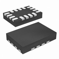
... MARKING ISL62870HRUZ GAL ISL62870HRUZ-T* GAL *Please refer to TB347 for details on reel specifications. NOTE: These Intersil Pb-free plastic packaged products employ special Pb-free material sets; molding compounds/die attach materials and NiPdAu plate - e4 termination finish, which is RoHS compliant and compatible with both SnPb and Pb-free soldering operations. Intersil Pb-free products are MSL classified at Pb-free peak reflow temperatures that meet or exceed the Pb-free requirements of IPC/JEDEC J STD-020 ...
Page 2
Block Diagram − SREF GND EN VCC POR V COMP RUN FAULT 100pF VSET − − OVP + FB FAULT − UVP VREF + 500mV FIGURE 1. SIMPLIFIED FUNCTIONAL BLOCK DIAGRAM ...
Page 3
Application Schematics R VCC +5V C PVCC GND GPIO NC 3 SREF 4 VCC GPIO FIGURE 2. ISL62870 APPLICATION SCHEMATIC WITH DCR CURRENT SENSE R VCC +5V C PVCC GND GPIO NC 3 SREF ...
Page 4
... Junction Temperature Range .-55°C to +150°C Operating Temperature Range . . . . . . . . . . . . . . . .-10°C to +100°C Storage Temperature . . . . . . . . . . . . . . . . . . . . . . . .-65°C to +150° -0. (DC) Pb-Free Reflow Profile .see link below -0. (<10ns) http://www.intersil.com/pbfree/Pb-FreeReflow.asp Recommended Operating Conditions - 0.3V (DC BOOT Ambient Temperature Range .-10°C to +100°C BOOT Converter Input Voltage to GND . . . . . . . . . . . . . . . . . . 3.3V to 25V VCC, PVCC to GND . . . . . . . . . . . . . . . . . . . . . . . . . . . . . . .5V ± ...
Page 5
Electrical Specifications These specifications apply for +25°C, VCC = 5V. Parameters with MIN and/or MAX limits are 100% tested at +25°C, unless otherwise A specified. Temperature limits established by characterization and are not production tested. (Continued) PARAMETER ...
Page 6
Functional Pin Descriptions GND (Pin 1) IC ground for bias supply and signal reference. EN (Pin 2) Enable input for the IC. Pulling EN above the V threshold voltage initializes the soft-start sequence. NC (Pins internal connection. ...
Page 7
V R OUT FB FB − + SREF FIGURE 4. ISL62870 VOLTAGE PROGRAMMING CIRCUIT Soft-Start Delay Circuit Description When the voltage on the VCC pin has ramped above the rising power-on reset voltage V VCC_THR the EN pin has increased ...
Page 8
... V UVTH Theory of Operation The modulator features Intersil’s R Regulator technology, a hybrid of fixed frequency PWM control and variable frequency hysteretic control. The PWM frequency is maintained at 300kHz under static continuous conduction mode operation within the entire specified ...
Page 9
VO pin. The positive slope of OUT V can be written as Equation 10 ⋅ ⁄ – V RPOS m IN OUT R The ...
Page 10
... The R IC makes the LC output filter resemble a first order system in which the closed loop stability can be achieved with the recommended Type-II compensation network. Intersil provides a PC-based tool that can be used to calculate compensation network component values and help simulate the loop frequency response ...
Page 11
... In addition to this guide, Intersil provides complete reference designs that include schematics, bills of materials, and example board layouts. Selecting the LC Output Filter The duty cycle of an ideal buck converter is a function of the input and the output voltage. This relationship is written as ...
Page 12
The bootstrap capacitor can be chosen from Equation 20: Q GATE ≥ C ----------------------- - ΔV BOOT BOOT Where the amount of gate charge required ...
Page 13
Where the difference of the DC component of the VALLEY inductor current minus 1/2 of the inductor ripple current - I is the sum of the DC component of the inductor PEAK current plus 1/2 of the ...
Page 14
Typical Performance 100 12. 19V (A) OUT FIGURE 13. EFFICIENCY AT V 1.0 ...
Page 15
Typical Performance (Continued) EN PGOOD 10s FIGURE 19. SHUT-DOWN 12.6V LOAD = OPEN-CIRCUIT VOUT PHASE UGATE LGATE FIGURE 21. DCM STEADY-STATE OPERATION 12.6V 1.0V OUT 1ADC FIGURE 23. DCM LOAD ...
Page 16
... Accordingly, the reader is cautioned to verify that data sheets are current before placing orders. Information furnished by Intersil is believed to be accurate and reliable. However, no responsibility is assumed by Intersil or its subsidiaries for its use; nor for any infringements of patents or other rights of third parties which may result from its use ...