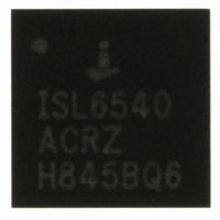
ISL6540AIRZ-T Intersil, ISL6540AIRZ-T Datasheet - Page 12

ISL6540AIRZ-T
Manufacturer Part Number
ISL6540AIRZ-T
Description
IC CTRLR PWM BUCK 1PHASE 28-QFN
Manufacturer
Intersil
Datasheet
1.ISL6540ACRZ-T.pdf
(22 pages)
Specifications of ISL6540AIRZ-T
Pwm Type
Voltage Mode
Number Of Outputs
1
Frequency - Max
2MHz
Duty Cycle
100%
Voltage - Supply
2.97 V ~ 22 V
Buck
Yes
Boost
No
Flyback
No
Inverting
No
Doubler
No
Divider
No
Cuk
No
Isolated
No
Operating Temperature
-40°C ~ 85°C
Package / Case
28-VQFN Exposed Pad, 28-HVQFN, 28-SQFN, 28-DHVQFN
Frequency-max
2MHz
Lead Free Status / RoHS Status
Lead free / RoHS Compliant
Power-Good
The power-good comparator references the voltage on the
soft-start pin to prevent accidental tripping during margining.
The trip points are shown in Figure 3. Additionally,
power-good will not be asserted until after the completion of
the soft-start cycle. A 0.1µF capacitor at the PG_DLY pin will
add an additional ~7ms delay to the assertion of power-good.
PG_DLY does not delay the de-assertion of power-good.
Under and Overvoltage Protection
The Undervoltage (UV) and Overvoltage (OV) protection
circuitry compares the voltage on the VMON pin with the
reference that tracks with the margining circuitry to prevent
accidental tripping. UV and OV functionality is not enabled
until the end of soft-start.
An OV event is detected asynchronously and causes the
high side MOSFET to turn off, the low side MOSFET to turn
on (effectively a 0% duty cycle), and PGOOD to pull low. The
regulator stays in this state and overrides sourcing and
sinking OCP protections until the OV event is cleared.
An UV event is detected asynchronously and results in the
PGOOD pulling low.
Overcurrent Protection
The ISL6540A monitors both the high side MOSFET and low
side MOSFET for overcurrent events. Dual sensing allows the
ISL6540A to detect overcurrent faults at the very low and very
high duty cycles that can result from the ISL6540A’s wide input
range. The OCP function is enabled with the drivers at startup
and detects the peak current during each sensing period. A
resistor and a capacitor between the LSOC pin and GND set
the low side source and sinking current limits. A 100µA current
source develops a voltage across the resistor which is then
compared with the voltage developed across the low side
MOSFET at conduction mode. The measurement comparator
uses offset correcting circuitry to provide precise current
measurements with roughly ±2mV of offset error. An ~120ns
blanking period, implemented on the upper and lower MOSFET
current sensing circuitries, is used to reduce the current
sampling error due to the leading-edge switching noise. An
additional 120ns low pass filter is used to further reduce
measurement error due to noise. In sourcing current
applications, the LSOC voltage is inverted and compared with
the voltage across the MOSFET while on. When this voltage
exceeds the LSOC set voltage, a sourcing OCP fault is
triggered. A 1000pF or greater filter capacitor should be used in
parallel with R
impacting the accuracy of the OCP measurement.
The ISL6540A’s sinking current limit is set to the same
voltage as its sourcing limit. In sinking applications, when the
voltage across the MOSFET is greater than the voltage
developed across the resistor (R
is triggered. To avoid non-synchronous operation at light
load, the peak-to-peak output inductor ripple current should
not be greater than twice of the sinking current limit.
LSOC
to prevent on-chip parasitics from
12
LSOC
) a sinking OCP event
ISL6540A
The high side sourcing current limit is set by connecting the
HSOC pin with a resistor (R
of the high side MOSEFT. A 100µA current source develops a
voltage across the resistor which is then compared with the
voltage developed across the high side MOSFET while on.
When the voltage drop across the MOSFET exceeds the
voltage drop across the resistor, a sourcing OCP event
occurs. A 1000pF or greater filter capacitor should be used in
parallel with R
impacting the accuracy of the OCP measurement and to
smooth the voltage across R
switching noise on the input bus.
Sourcing OCP faults cause the regulator to disable (Ugate and
Lgate drives pulled low, PGOOD pulled low, soft-start capacitor
discharged) itself for a fixed period of time after which a normal
soft-start sequence is initiated. The period of time the regulator
waits before attempting a soft-start sequence is set by three
charge and discharge cycles of the soft-start capacitor.
Sinking OCP faults cause the low side MOSFET drive to be
disabled, effectively operating the ISL6540A in a
non-synchronous manner. The fault is maintained for three
clock cycles at which point it is cleared and normal operation
is restored. OVP fault implementation overrides sourcing
and sinking OCP events, immediately turning on the low side
MOSFET and turning off the high side MOSFET. The OC trip
Detailed Low Side OCP Equations
R
ΔI =
I
N
Detailed High Side OCP Equation
R
N
Simple High Side OCP Equation
R
Simple Low Side OCP Equation
R
OC_SINK
LSOC
L
HSOC
U
HSOC
LSOC
=
=
V
------------------------------- -
Number of low side MOSFETs
Number of high side MOSFETs
IN
=
F
=
=
=
- V
S
=
⎛
⎝
------------------------------------------------------------------------------------- -
⎛
⎝
-------------------------------------------------------------------------------------- -
I
-------------------------------------------------------------------------------------- -
I
---------------------------------------------------------------------------------------- -
I
OC_SOURCE
OC_SOURCE
I
L
OC_SOURCE
OUT
I
------------------------------------------------------- -
OC_SOURCE
LSOC
HSOC
•
r
DS ON
V
--------------- -
•
V
OUT
I
I
N
to prevent on-chip parasitics from
LSOC
IN
(
HSOC
L
100μA
100μA
•
r •
r •
+
),L
+
R
DS ON
I Δ
---- -
DS ON
2
I Δ
---- -
LSOC
•
2
•
HSOC
⎞
⎠
N
⎞
⎠
N
HSOC
(
(
r •
L
r •
U
DS ON
DS ON
)LowSide
–
)HighSide
) and a capacitor to the drain
I Δ
---- -
(
2
(
in the presence of
),L
),U
October 7, 2008
(EQ. 4)
(EQ. 2)
FN6288.5
(EQ. 3)
(EQ. 5)


