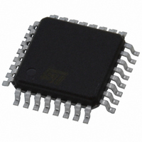
L5994A STMicroelectronics, L5994A Datasheet - Page 11

L5994A
Manufacturer Part Number
L5994A
Description
IC CTRLR PS ADJ TRPL-OUT 32-TQFP
Manufacturer
STMicroelectronics
Datasheet
1.L5994.pdf
(26 pages)
Specifications of L5994A
Pwm Type
Current Mode
Number Of Outputs
3
Frequency - Max
345kHz
Duty Cycle
96%
Voltage - Supply
4.75 V ~ 25 V
Buck
Yes
Boost
No
Flyback
Yes
Inverting
No
Doubler
No
Divider
No
Cuk
No
Isolated
No
Operating Temperature
-40°C ~ 140°C
Package / Case
32-TQFP, 32-VQFP
Frequency-max
345kHz
Lead Free Status / RoHS Status
Lead free / RoHS Compliant
Other names
497-5340
L5994A
L5994A
Available stocks
Company
Part Number
Manufacturer
Quantity
Price
L5994 - L5994A
Protections
Each converter is fully protected against fault conditions. A monitoring system checks for overvoltages of the
output, quickly disabling the interested converter in case such an event occurs. This condition is latched and to
allow the device to start again either the supply voltages have to be removed or the relative RUNx pin has to be
driven low.
Also the undervoltage conditions are detected: a light undervoltage (90% of the programmed value) only causes
the relative PWROKx to be driven low while an hard undervolatge (70% of the programmed value) causes in-
terruption of the operation of both converters. This is a protection against short circuits.
PWROKx signals (at pin 10 and 23) reveals the anomaly of the relative section (output voltage not within the
±10% of the programmed voltage) with a low output level. If the chip overheats (above 135°C typ.) the device
stops operating as long as the temperature falls below a safe value (105°C typ.). The overtemperature condition
is signalled by a low level on both PWROKx as well.
A current limitation comparator prevents from excessive current in case of overload. It intervenes as the voltage
VRSENSE exceeds 50mV, turning off the high-side switch before the error summing does. By the way, this also
gives the designer the ability to program the maximum operating current by selecting an appropriate sense re-
sistor. This pulse-by-pulse limitation gives a quasi-constant current characteristic.
Linear Driver
The Linear driver is capable of sinking up to 60mA from an external PNP transistor through the pin VDRLIN
considering the typical application circuit shown in fig. 4. The internal comparator is supplied by the same pin
VDRLIN which accepts voltages included in the range from 4.5V to 20V. If the application works with input volt-
ages that allows the regulation, the supply for the regulator can be obtained directly from the input source (VIN).
If such is not the case and is not available an additional input voltage, the most convenient way to get the supply
is to use an auxiliary winding on one of the two sections inductor with a catch diode, DS, and a filter capacitor,
CS, as shown in fig. 5. This winding delivers energy to pin VDRLIN during the recirculation period of each switch-
ing cycle with a voltage determined by the turns ratio n and little dependent on the input voltage.
Figure 4. Linear regulator supply with auxiliary winding
Vcc
2.5V
Vout
VDRLIN
VFBLIN
L5994
In case the section with the auxiliary winding is working at full load and the linear regulator is lightly loaded, the
voltage at pin VDRLIN can exceed the expected value. In fact, DS and CS act as a peak-holding circuit and
VDRLIN is influenced by the voltage spikes at switching transients. An internal clamp limits the voltage on the
VDRLIN pin at a maximum value of 16V, but, in case of intervention, the chip power dissipation will rise.The
linear driver is always active as long as PREG5 and VREF are present on the chip (see the relevant section); it
11/26


