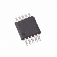
EL7512CYZ-T7 Intersil, EL7512CYZ-T7 Datasheet - Page 6

EL7512CYZ-T7
Manufacturer Part Number
EL7512CYZ-T7
Description
IC REG PWM STEP-UP 10-MSOP
Manufacturer
Intersil
Datasheet
1.EL7512CY.pdf
(8 pages)
Specifications of EL7512CYZ-T7
Pwm Type
Controller
Number Of Outputs
1
Frequency - Max
1.2MHz
Duty Cycle
90%
Voltage - Supply
2 V ~ 12 V
Buck
No
Boost
Yes
Flyback
No
Inverting
No
Doubler
No
Divider
No
Cuk
No
Isolated
No
Operating Temperature
-40°C ~ 85°C
Package / Case
10-MSOP, Micro10™, 10-uMAX, 10-uSOP
Frequency-max
1.2MHz
Lead Free Status / RoHS Status
Lead free / RoHS Compliant
Applications Information
The EL7512 is a step-up regulator, operated at fixed
frequency pulse-width-modulation (PWM) control. The input
voltage is 2V-12V and output voltage is 5V-18V. The
switching frequency (up to 1.2MHz) is decided by the
resistor connected to RT pin.
Start-Up
After V
oscillator generates fixed duty-ratio of 0.5-0.7 at a frequency
of several hundred kilohertz. This will boost the output
voltage.
When V
over the control. The duty ratio will be decided by the
multiple-input direct summing comparator, Max_Duty signal
(about 90% duty-ratio), and the Current Limit Comparator,
whichever is the smallest.
The soft-start is provided by the current limit comparator. As
the internal 12µA current source charges the external CSS,
the peak MOSFET current is limited by the voltage on the
capacitor. This in turn controls the rising rate of the output
voltage.
The regulator goes through the start-up sequence as well
after the EN signal is pulled to HI.
Steady-State Operation
When the output reaches the preset voltage, the regulator
operates at steady state. Depending on the input/output
conditions and component values, the inductor operates at
either continuous-conduction mode or discontinuous-
conduction mode.
In the continuous-conduction mode, the inductor current is a
triangular waveform and LX voltage a pulse waveform. In the
discontinuous-conduction mode, the inductor current is
completely dried out before the MOSFET is turned on again.
The input voltage source, the inductor, and the MOSFET and
output diode parasitic capacitors forms a resonant circuit.
Oscillation will occur in this period. This oscillation is normal
and will not affect the regulation.
At very low load, the MOSFET will skip pulses sometimes.
This is normal.
Current Limit
The MOSFET current limit is nominally 1.2A and guaranteed
1A. This restricts the maximum output current I
on the following formula:
DD
DD
reaches a threshold of about 2V, the start-up
reaches about 3.7V, the PWM comparator takes
I
OMAX
=
1
6
–
∆I
--------
2
L
×
V
---------
V
IN
O
OMAX
based
EL7512
where:
The following table gives typical values:
Component Considerations
It is recommended that C
Theoretically, the input capacitor has ripple current of ∆I
Due to high-frequency noise in the circuit, the input current
ripple may exceed the theoretical value. Larger capacitor will
reduce the ripple further.
The inductor has peak and average current decided by:
The inductor should be chosen to be able to handle this
current. Furthermore, due to the fixed internal
compensation, it is recommended that maximum inductance
of 10µH and 15µH to be used in the 5V and 12V or higher
output voltage, respectively.
The output diode has average current of I
current the same as the inductor's peak current. Schottky
∆I
decided by:
D is the MOSFET turn-on ratio and is decided by:
F
V
S
L
IN
3.3
3.3
3.3
12
12
2
2
2
5
5
5
9
9
is the switching frequency.
is the inductor peak-to-peak current ripple and is
(V)
MAX CONTINUOUS OUTPUT CURRENTS
I
I
LPK
LAVG
V
=
O
12
12
12
15
12
15
15
18
5
9
5
9
9
=
I
(V)
LAVG
------------ -
1 D
I
–
O
∆I
D
+
L
IN
=
∆I
--------
=
2
L (µH)
is larger than 10µF.
L
V
----------------------- -
10
10
10
10
10
10
10
10
10
10
10
10
11
V
---------
O
L
IN
V
–
O
×
V
IN
------ -
F
D
S
F
S
1000
1000
1000
1000
1000
1000
1000
1000
1000
1000
1000
1000
1000
(kHz)
O
, and peak
I
OMAX
(mA)
360
190
140
600
310
230
470
340
260
630
470
670
510
L
.


