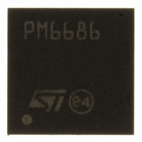
PM6686TR STMicroelectronics, PM6686TR Datasheet - Page 24

PM6686TR
Manufacturer Part Number
PM6686TR
Description
IC CTLR DUAL STEP DOWN VFQFPN32
Manufacturer
STMicroelectronics
Datasheet
1.PM6686TR.pdf
(50 pages)
Specifications of PM6686TR
Applications
Controller, Notebook Computers
Voltage - Input
5.5 ~ 28 V
Number Of Outputs
2
Operating Temperature
-40°C ~ 85°C
Mounting Type
Surface Mount
Package / Case
32-VFQFN, 32-VFQFPN
Output Voltage
5.5 V
Output Current
100 mA
Output Power
4.3 mW
Input Voltage
5.5 V to 28 V
Switching Frequency
33 KHz
Mounting Style
SMD/SMT
Maximum Operating Temperature
+ 85 C
Minimum Operating Temperature
- 40 C
Lead Free Status / RoHS Status
Lead free / RoHS Compliant
Voltage - Output
-
Lead Free Status / Rohs Status
Lead free / RoHS Compliant
Other names
497-8522-2
Available stocks
Company
Part Number
Manufacturer
Quantity
Price
Company:
Part Number:
PM6686TR
Manufacturer:
st
Quantity:
2 069
Part Number:
PM6686TR
Manufacturer:
ST
Quantity:
20 000
Device description
8
8.1
8.1.1
24/50
Device description
The PM6686 is a dual step down controller dedicated to provide logic voltages for notebook
computers. It offers several operating configurations: it combines two synchronous buck
controllers, an internal linear regulator (LDO), two voltage references and a charge pump
controller.
Each buck controller is based on constant on time (COT) architecture. This type of control
offers a very fast load transient response with a minimum external components count.
The two switching sections (SMPS) generate two output voltages OUT1 and OUT2 that
regulate adjustable voltages. A fixed output voltage configuration can also be selected,
reducing further the external components count because no external resistor divider is
needed.
In fixed mode, OUT1 provides 5 V or 1.5 V; in adjustable mode OUT1 can regulate an output
voltage between 0.7 V and 5.5 V. In fixed mode, OUT2 provides 3.3 V or 1.05 V, in
adjustable mode OUT2 can regulate an output between 0.7 V to 2.5 V by tracking an
external reference.
The switching frequencies of both switching controllers can be adjusted to 200 kHz/300 kHz,
400 kHz/300 kHz or 400 kHz/500 kHz respectively. To maximize the efficiency at light loads
a pulse skipping mode can be selected. Moreover a pulse skipping mode with a minimum
switching frequency of 33 kHz (non audible skip operation mode) can be selected to avoid
audible noise issue. The linear regulator can provide a fixed (5 V or 3.3 V) or an adjustable
output voltage. In order to reduce the power consumption the internal LDO can be turned off
and the LDO output can be supplied with an external voltage applied at LDO_SW pin
(switch-over function).
The PM6686 supplies two voltage references: 3.3 V and 2 V. The charge pump controller
can be programmed to regulate a 14 V output. The switching sections and the LDO have
independent enable signals. Moreover the switching sections have a selectable power up
sequence and a turn off management.
The device is protected against overvoltage, undervoltage and over temperature. Two
independent Power Good signals monitor the output voltage range of each switching
sections.
Switching sections
Output voltage set up
The switching sections can be configured in several ways.
OUT1 output voltage is configured with FB1 pin. If FB1 pin is tied to GND the PM6686
regulates 5 V while if FB1 is connected to VCC the controller set OUT1 at 1.5 V. Using an
external resistor divider the output can be adjusted following this equation:
Equation 1
Doc ID 15281 Rev 4
V
OUT
1
=
0
7 ,
V
⋅
⎛
⎜
⎝
R
R
1
2
+
1
⎞
⎟
⎠
PM6686


