ISL6423ERZ-T Intersil, ISL6423ERZ-T Datasheet - Page 10
ISL6423ERZ-T
Manufacturer Part Number
ISL6423ERZ-T
Description
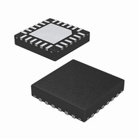
IC VREG SGL LNB W/I2C 24-QFN
Manufacturer
Intersil
Datasheet
1.ISL6423ERZ.pdf
(16 pages)
Specifications of ISL6423ERZ-T
Applications
Converter, Satellite Set-Top Box Designs
Voltage - Input
8 ~ 14 V
Number Of Outputs
1
Voltage - Output
13.3 ~ 18.3 V, 14.3 ~ 19.3 V
Operating Temperature
-20°C ~ 85°C
Mounting Type
Surface Mount
Package / Case
24-VQFN
Lead Free Status / RoHS Status
Lead free / RoHS Compliant
Available stocks
Company
Part Number
Manufacturer
Quantity
Price
Company:

Part Number:
ISL6423ERZ-T
Manufacturer:
JMICRON
Quantity:
256


However, there could be some cases in which a highly
capacitive load on the output may cause a difficult start-up
when the dynamic protection is selected. This can be solved
by initiating any power start-up in static mode (DCL = HIGH)
and then switching to the dynamic mode (DCL = LOW) after
a predetermined interval. When in static mode, the OLF bit
goes HIGH when the current clamp limit is reached and
returns LOW when the overload condition is cleared. The
OLF/BCF bit will be LOW at the end of initial power-on soft-
start. In the static mode the output current through the linears
is limited to a 990mA typical.
When a 19.3V line is connected onto a VOUT1 or 2 that has
been set to 13.3V the linear will then enter a back current
limited state. When a back current of greater than 125mA
typical is sensed at the lower FET of the linear for a period
greater that 100µs, the output is disabled for a period of 5ms
and the BCF bit is set. If the 19.3V remains connected, the
output will cycle through the ON = 100µs/OFF = 5ms. The
output will recover when the fault is removed.
Thermal Protection
This IC is protected against overheating. When the junction
temperature exceeds 150°C (typical), the step-up converter
and the linear regulator are shut off and the OTF bit of the
SR is set HIGH. When the junction is cooled down to +130°C
(typical), normal operation is resumed and the OTF bit is
reset LOW.
In over temperature conditions, the OTF flag goes HIGH and
the I
the I
the chip, if I
make the OLF flags go HIGH, when high capacitive loads
are present or self-heating conditions occur at higher loads.
External Output Voltage Selection
When the I
be selected by the I
the pin SELVTOP for independent 13V thru 19V output
voltage selection, when the VSPEN bit is set low. A
summary of the voltage control is given in the Table 1. For
further details refer to the individual registers SR1 and SR3
VSPEN
2
2
0
0
0
0
1
1
1
1
C data will be cleared. The user may need to monitor
C enable bits and OTF flag continuously and enable
2
2
C bit VSPEN is set high the output voltage can
C data is cleared. OTF conditions may also
VTOP
0
1
0
0
1
1
x
x
2
C bus. Additionally, the package offers
TABLE 1.
VBOT
10
0
1
0
1
0
1
x
x
SELVTOP
0
0
1
1
x
x
x
x
VOUT (V)
13.3
14.3
18.3
19.3
13.3
14.3
18.3
19.3
ISL6423
I
(Refer to Philips I
Data transmission from main microprocessor to the ISL6423
and vice versa takes place through the two wire I
interface, consisting of the two lines SDA and SCL. Both
SDA and SCL are bidirectional lines, connected to a positive
supply voltage via a pull up resistor. (Pull-up resistors to
positive supply voltage must be externally connected). When
the bus is free, both lines are HIGH. The output stages of
ISL6423 will have an open drain/open collector in order to
perform the wired-AND function. Data on the I
transferred up to 100kbps in the standard-mode or up to
400kbps in the fast-mode. The level of logic “0” and logic “1”
is dependent of associated value of V
specification table. One clock pulse is generated for each
data bit transferred.
Data Validity
The data on the SDA line must be stable during the HIGH
period of the clock. The HIGH or LOW state of the data line
can only change when the clock signal on the SCL line is
LOW. Refer to Figure 4.
START and STOP Conditions
As shown in Figure 5, START condition is a HIGH to LOW
transition of the SDA line while SCL is HIGH.
The STOP condition is a LOW to HIGH transition on the SDA
line while SCL is HIGH. A STOP condition must be sent
before each START condition.
2
SDA
SCL
SDA
SCL
C Bus Interface for ISL6423
CONDITION
START
S
FIGURE 5. START AND STOP WAVEFORMS
DATA VALID
DATA LINE
STABLE
2
FIGURE 4. DATA VALIDITY
C Specification, Rev. 2.1)
ALLOWED
CHANGE
OF DATA
DD
as per electrical
2
C bus can be
December 5, 2008
CONDITION
2
C bus
STOP
P
FN9191.2
Related parts for ISL6423ERZ-T
Image
Part Number
Description
Manufacturer
Datasheet
Request
R

Part Number:
Description:
Single Output Lnb Supply And Control Voltage Regulator With I2c Interface For Advanced Satellite Set-top Box Designs, Diseqc 2.0 Compatible
Manufacturer:
Intersil Corporation
Datasheet:
Part Number:
Description:
Intersil Corporation [CMOS Serial Controller Interface]
Manufacturer:
Intersil Corporation
Datasheet:
Part Number:
Description:
Manufacturer:
Intersil Corporation
Datasheet:
Part Number:
Description:
357-036-542-201 CARDEDGE 36POS DL .156 BLK LOPRO
Manufacturer:
Intersil Corporation
Datasheet:
Part Number:
Description:
1024-Word x 4-Bit LSI Static RAM
Manufacturer:
Intersil Corporation
Datasheet:
Part Number:
Description:
General Purpose NPN Transistor Arrays FN341.4
Manufacturer:
Intersil Corporation
Datasheet:
Part Number:
Description:
CMOS 16-Bit Microprocessor
Manufacturer:
Intersil Corporation
Datasheet:
Part Number:
Description:
Manufacturer:
Intersil Corporation
Datasheet:
Part Number:
Description:
Manufacturer:
Intersil Corporation
Datasheet:
Part Number:
Description:
Manufacturer:
Intersil Corporation
Datasheet:
Part Number:
Description:
Manufacturer:
Intersil Corporation
Datasheet:
Part Number:
Description:
CMOS 6-Bit Latch and Decoder Memory Interfaces
Manufacturer:
Intersil Corporation
Datasheet:
Part Number:
Description:
CA3046General Purpose NPN Transistor Arrays
Manufacturer:
Intersil Corporation
Datasheet:
Part Number:
Description:
Manufacturer:
Intersil Corporation
Datasheet:
Part Number:
Description:
TR909 DLC/FLC SLIC with Low Power Standby
Manufacturer:
Intersil Corporation
Datasheet: