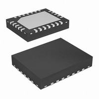
ISL8101IRZ Intersil, ISL8101IRZ Datasheet - Page 7

ISL8101IRZ
Manufacturer Part Number
ISL8101IRZ
Description
IC PWM CTRLR BUCK 2PHASE 24-QFN
Manufacturer
Intersil
Datasheet
1.ISL8101CRZ-T.pdf
(20 pages)
Specifications of ISL8101IRZ
Applications
Controller, Intel VRM9, VRM10, and AMD Hammer Applications
Voltage - Input
4.6 ~ 12 V
Number Of Outputs
1
Voltage - Output
0.6 ~ 2.3 V
Operating Temperature
-40°C ~ 85°C
Mounting Type
Surface Mount
Package / Case
24-VQFN Exposed Pad, 24-HVQFN, 24-SQFN, 24-DHVQFN
Lead Free Status / RoHS Status
Lead free / RoHS Compliant
Operation
The ISL8101 employs simple voltage-mode control. Figure 1
shows a simplified diagram of the voltage regulation and
current balance loops. Voltage feedback is used to precisely
regulate the output voltage, while current feedback tightly
controls the individual channel currents, I
trips the OC protection, if so necessary.
VOLTAGE LOOP
Feedback from the output voltage is applied via resistor R
to the inverting input of the Error Amplifier. This signal can
drive the Error Amplifier output either high or low, depending
upon the output voltage. Low output voltage makes the
amplifier output move towards a higher output voltage level.
Amplifier output voltage is applied to the positive inputs of
the PWM Circuit comparators via the channel current
correction summing networks. Out-of-phase sawtooth
signals are applied to the two PWM comparators inverting
inputs. Increasing Error Amplifier voltage results in increased
Comparator output duty cycle. This increased duty cycle
signal is passed through the output drivers with no phase
reversal to drive the external upper MOSFETs. Increased
duty cycle or ON time for the upper MOSFET transistors
results in increased output voltage to compensate for the low
output voltage sensed.
COMP
R
R
C
FB
2
1
2
ISL8101
FIGURE 1. SIMPLIFIED BLOCK DIAGRAM OF THE ISL8101 VOLTAGE AND CURRENT FEEDBACK
ERROR
REFERENCE
AMP
DAC
AND
7
Σ
Σ
OSCILLATOR
L1
and I
Σ
Σ
L2
, and
AVERAGE
CIRCUIT
CIRCUIT
PWM
PWM
1
ISL8101
ISL8101
CHANNEL BALANCE CURRENT LOOP
The current balance control loop works in a similar fashion to
the voltage control loop, but with current control information
applied individually to each channel’s PWM circuit. The
information used for this control is the voltage that is
developed across the r
they are conducting. A single resistor converts and scales
the voltage across the MOSFETs to a current that is applied
to the Current Sensing circuit within the ISL8101. Output
from these sensing circuits is applied to the current
averaging circuit. Each PWM channel receives the
difference current signal from the summing circuit that
compares the average sensed current to the individual
channel current. When a power channel’s current is greater
than the average current, the signal applied via the summing
Correction circuit to the Comparator, reduces the output
pulse width of the Comparator to compensate for the
detected “above average” current in that channel.
MULTIPHASE POWER CONVERSION
Multiphase power conversion provides a cost-effective
power solution when load currents are no longer easily
supported by single-phase converters. Although its greater
complexity presents additional technical challenges, the
multiphase approach offers cost-saving advantages with
improved response time, superior ripple cancellation, and
thermal distribution.
CURRENT
CURRENT
HALF-BRIDGE
HALF-BRIDGE
SENSE
SENSE
DRIVE
DRIVE
LGATE2
UGATE1
UGATE2
DS(ON)
LGATE1
PHASE1
PHASE2
ISEN
R
ISEN
of each lower MOSFET, while
V
V
IN
IN
V
L
L
CC
2
1
July 28, 2008
C
V
OUT
FN9223.1
OUT


