LNBH21PD STMicroelectronics, LNBH21PD Datasheet
LNBH21PD
Specifications of LNBH21PD
Available stocks


Related parts for LNBH21PD


LNBH21PD Summary of contents
Page 1
STEP-UP CONVERTER AND I COMPLETE INTERFACE BETWEEN LNB 2 TM AND I C BUS BUILT-IN DC/DC CONTROLLER FOR SINGLE 12V SUPPLY OPERATION AND HIGH EFFICIENCY (Typ. 94% @ 750mA) TWO SELECTABLE OUTPUT CURRENT LIMIT (450mA / 750mA) BOTH COMPLIANT WITH ...
Page 2
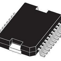
... Absolute Maximum Ratings are those values beyond which damage to the device may occur. Functional operation under these condition is not implied. THERMAL DATA Symbol R Thermal Resistance Junction-case thj-case PIN CONFIGUARATION (top view) 2/20 PowerSO-20 (Tube) LNBH21PD Parameter Parameter PowerSO-20 (Tape & Reel) LNBH21PD-TR Value Unit -0 -0 Internally Limited ...
Page 3
TABLE A: PIN CONFIGURATIONS PIN N° SYMBOL NAME 18 V Supply Input CC 17 GATE External Switch Gate 16 SENSE Current Sense Input 19 V Step-up Voltage Output Port during O 22KHz Tone RX 12 SDA ...
Page 4
LNBH21 TYPICAL APPLICATION CIRCUITS Application Circuit for DiSEqC 1.x and Output Current < 450 mA Ferrite Bead Filter Ferrite Bead Filter F1 F1 suggested part number: suggested part number: MURATA BL01RN1-A62 MURATA BL01RN1-A62 Panasonic EXCELS A35 Panasonic EXCELS A35 C2 ...
Page 5
APPLICATION INFORMATION This IC has a built in DC/DC step-up controller that, from a single supply source ranging from 8 to 15V, generates the voltages (V ) that let the linear post-regulator to work at a minimum dissipated power of ...
Page 6
LNBH21 However, there could be some cases in which an highly capacitive load on the output may cause a difficult start-up when the dynamic protection is chosen. This can be solved by initiating any power start-up in static mode (PCL=HIGH) ...
Page 7
Figure 2 : TIMING DIAGRAM ON I Figure 3 : ACKNOWLEDGE ON I LNBH21 SOFTWARE DESCRIPTION INTERFACE PROTOCOL The interface protocol comprises start condition ( chip address byte = hex (the LSB bit ...
Page 8
LNBH21 2 TRANSMITTED DATA (I C BUS WRITE MODE) When the R/W bit in the chip address is set to 0, the main µP can write on the System Register (SR) of the 2 LNBH21 via I C bus. Only ...
Page 9
DiSEqCTM IMPLEMENTATION The LNBH21 helps the system designer to implement the bi-directional (2.0) DiSEqC protocol by allowing an easy PWK modulation/demodulation of the 22KHz carrier. The PWK data are exchanged between the LNBH21 and the main µP using logic levels ...
Page 10
LNBH21 ELECTRICAL CHARACTERISTICS FOR LNBP SERIES (T LLC=TEN=PCL=VSEL= section for I C access to the system register). Symbol Parameter V Supply Voltage IN I Supply Current I V Output Voltage O V Output Voltage O V Line ...
Page 11
GATE AND SENSE ELECTRICAL CHARACTERISTICS (T Symbol Parameter R Gate LOW R DSON-L DSON R Gate HIGH R DSON-H DSON V Current Limit Sense Voltage SENSE ELECTRICAL CHARACTERISTICS (T Symbol Parameter V LOW Level Input Voltage IL ...
Page 12
LNBH21 THERMAL DESIGN NOTES During normal operation, the LNBH21 device dissipates some power. At maximum rated output current (750mA), the voltage drop on the linear regulator lead to a total dissipated power that is typically 1.65W. The heat generated requires ...
Page 13
TYPICAL CHARACTERISTICS (unless otherwise specified T Figure 5 : Output Voltage vs Temperature Figure 6 : Output Voltage vs Temperature Figure 7 : Output Voltage vs Temperature = 25°C) j Figure 8 : Load Regulation vs Temperature Figure 9 : ...
Page 14
LNBH21 Figure 11 : Supply Current vs Temperature Figure 12 : Supply Current vs Temperature Figure 13 : Dynamic Overload Protection ON Time vs Temperature 14/20 Figure 14 : Dynamic Overload Protection OFF Time vs Temperature Figure 15 : Output ...
Page 15
Figure 17 : Tone Frequency vs Temperature Figure 18 : Tone Amplitude vs Temperature Figure 19 : Tone Duty Cycle vs Temperature Figure 20 : Tone Rise Time vs Temperature Figure 21 : Tone Fall Time vs Temperature Figure 22 ...
Page 16
LNBH21 Figure 23 : Output Backward Current vs Temperature Figure 24 : DC/DC Converter Efficiency vs Temperature Figure 25 : Current Limit Sense Voltage vs Temperature 16/20 Figure 26 : 22kHz Tone Waveform V =12V, I =50mA, EN=TEN ...
Page 17
Figure 29 : DSQIN Tone Disable Transient Response V =12V, I =50mA, EN=1, Tone enabled by DSQIN Pin CC O LNBH21 17/20 ...
Page 18
LNBH21 DIM. MIN 0. 0.40 c 0.23 D (1) 15.80 E 13. (1) 10. 0. 0˚ T (1) “D and E1” do not include ...
Page 19
Tape & Reel PowerSO-20 MECHANICAL DATA mm. DIM. MIN 12 15.1 Bo 16.5 Ko 3.8 Po 3.9 P 23.9 W 23.7 TYP MAX. MIN. 330 13.2 0.504 0.795 2.362 30.4 15.3 0.594 ...
Page 20
... No license is granted by implication or otherwise under any patent or patent rights of STMicroelectronics. Specifications mentioned in this publication are subject to change without notice. This publication supersedes and replaces all information previously supplied ...