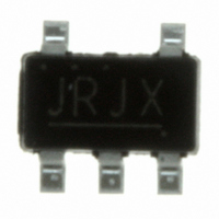
S-8354A50MC-JRJT2G Seiko Instruments, S-8354A50MC-JRJT2G Datasheet - Page 24

S-8354A50MC-JRJT2G
Manufacturer Part Number
S-8354A50MC-JRJT2G
Description
IC SWITCHING REG 5.0V SOT-23-5
Manufacturer
Seiko Instruments
Type
Step-Up (Boost)r
Datasheet
1.S-8354A33MC-JQST2G.pdf
(49 pages)
Specifications of S-8354A50MC-JRJT2G
Internal Switch(s)
Yes
Synchronous Rectifier
No
Number Of Outputs
1
Voltage - Output
5V
Frequency - Switching
50kHz
Voltage - Input
0.9 ~ 10 V
Operating Temperature
-40°C ~ 85°C
Mounting Type
Surface Mount
Package / Case
SOT-23-5, SC-74A, SOT-25
Power - Output
250mW
Output Voltage
5 V
Input Voltage
10 V
Duty Cycle (max)
90 %
Switching Frequency
50 KHz
Mounting Style
SMD/SMT
Primary Input Voltage
5.5V
No. Of Outputs
1
Output Current
320mA
No. Of Pins
5
Operating Temperature Range
-40°C To +85°C
Operating Temperature Min
85°C
Rohs Compliant
Yes
Lead Free Status / RoHS Status
Lead free / RoHS Compliant
Current - Output
-
Lead Free Status / Rohs Status
Lead free / RoHS Compliant
Other names
728-1036-2
Available stocks
Company
Part Number
Manufacturer
Quantity
Price
Part Number:
S-8354A50MC-JRJT2G
Manufacturer:
SEMTECH/美国升特
Quantity:
20 000
24
STEP-UP, PWM CONTROL or PWM / PFM SWITCHABLE BUILT-IN TRANSISTOR SWITCHING REGULATOR
S-8353/8354 Series
Precautions
• Mount external capacitors, diodes, and coils as close as possible to the IC. Especially, mounting the output capacitor
• Characteristics ripple voltage and spike noise occur in IC containing switching regulators. Moreover rush current flows
• Make sure that the dissipation of the switching transistor (especially at a high temperature) does not exceed the
• The performance of this IC varies depending on the design of the PCB patterns, peripheral circuits and external parts.
• Do not apply an electrostatic discharge to this IC that exceeds the performance ratings of the built-in electrostatic
• SII claims no responsibility for any and all disputes arising out of or in connection with any infringement of the products
(capacitor between VDD pin and VSS pin for V
can enable stable output characteristics. If it is impossible, it is recommended to mount and wire a ceramic capacitor
of around 0.1 μF close to the IC.
at the time of a power supply injection. Because these largely depend on the coil, the capacitor and impedance of
power supply used, fully check them using an actually mounted model.
allowable power dissipation of the package.
Thoroughly test all settings with your device. The recommended external part should be used wherever possible, but if
this is not possible for some reason, contact an SII sales person.
protection circuit.
including this IC upon patents owned a third party.
Seiko Instruments Inc.
DD
/ V
OUT
separate type) in the power supply line of the IC close to the IC
Rev.3.0
_00


