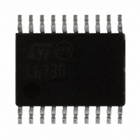
L6730TR STMicroelectronics, L6730TR Datasheet - Page 31

L6730TR
Manufacturer Part Number
L6730TR
Description
IC CTRLR ADJ STEP DOWN 20-TSSOP
Manufacturer
STMicroelectronics
Type
Step-Down (Buck)r
Datasheet
1.L6730TR.pdf
(52 pages)
Specifications of L6730TR
Internal Switch(s)
No
Synchronous Rectifier
Yes
Number Of Outputs
1
Voltage - Output
Adj to 0.6V
Frequency - Switching
100kHz ~ 1MHz
Voltage - Input
1.8 ~ 14 V
Operating Temperature
-40°C ~ 85°C
Mounting Type
Surface Mount
Package / Case
20-TSSOP Exposed Pad, 20-eTSSOP, 20-HTSSOP
Output Voltage
0.6 V
Input Voltage
1.8 V to 14 V
Maximum Operating Temperature
+ 85 C
Minimum Operating Temperature
- 40 C
For Use With
497-5868 - EVAL BOARD 30A 400KHZ L6730497-5501 - EVAL BOARD FOR L6730XX
Lead Free Status / RoHS Status
Lead free / RoHS Compliant
Current - Output
-
Power - Output
-
Lead Free Status / Rohs Status
Lead free / RoHS Compliant
Other names
497-5098-2
Available stocks
Company
Part Number
Manufacturer
Quantity
Price
Part Number:
L6730TR
Manufacturer:
ST
Quantity:
20 000
L6730 - L6730B
5.14.1
5.14.2
Fan power supply failure
In many applications the fan is driven by a DC motor that uses a DC/DC converter. Often
only the speed of the motor is controlled by varying the voltage applied to the input terminal
and there is no control on the torque because the current is not directly controlled. The
current has to be limited in case of overload or short-circuit, but without stopping the motor.
With the L6730B, the current can be limited without shutting down the system because
constant current protection is provided. In order to vary the motor speed, the output voltage
of the converter must be varied. Both L6730 and L6730B have a dedicated EAREF pin (see
Figure
amplifier.
In these applications the duty cycle depends on the motor’s speed and sometimes a 100%
duty cycle setting has to be used to attain the maximum speed. In these conditions, the
bootstrap capacitor can not be recharged and the system cannot work properly. Some PWM
controllers limit the maximum duty cycle to 80 or 90% in order to keep the bootstrap
capacitor charged, but this makes performance during the load transient worse. The
“bootstrap anti-discharging system” allows the L6730x to work at 100% without any
problem.
Figure 26.: 100% duty cycle operation on page 31
device behavior when the input voltage is 5 V and a 100% duty cycle is set by an external
reference.
Figure 26. 100% duty cycle operation
No-sink at zero current operation
The L6730 can work in no-sink mode. If output current is zero the converter skip some
pulses and works with a lower switching frequency. Between two pulses can pass a
relatively long time (say 200-300 µs) during which there’s no switching activity and the
current into the inductor is zero. In this condition the phase node is at the output voltage and
in some cases this is not enough to keep the bootstrap cap charged. For example, if Vout is
3.3 V the voltage across the bootstrap cap is only 1.7 V. The high-side MOSFET cannot be
4) which provides an external reference to the non-inverting input of the error-
TOFF≈200ns
Doc ID 11938 Rev 3
shows the following picture illustrates the
Vout=5V
Vin=5V
LGate
Fsw?6.3KHz
Device description
≈
31/52


