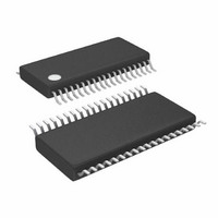
LTC3865EFE#TRPBF Linear Technology, LTC3865EFE#TRPBF Datasheet - Page 17

LTC3865EFE#TRPBF
Manufacturer Part Number
LTC3865EFE#TRPBF
Description
IC BUCK SYNC ADJ DUAL 38TSSOP
Manufacturer
Linear Technology
Type
Step-Down (Buck)r
Datasheet
1.LTC3865EUHPBF.pdf
(38 pages)
Specifications of LTC3865EFE#TRPBF
Internal Switch(s)
No
Synchronous Rectifier
Yes
Number Of Outputs
2
Voltage - Output
0.6 ~ 5 V
Frequency - Switching
250kHz ~ 770kHz
Voltage - Input
4.5 ~ 38 V
Operating Temperature
-40°C ~ 85°C
Mounting Type
Surface Mount
Package / Case
38-TSSOP Exposed Pad, 38-eTSSOP, 38-HTSSOP
Lead Free Status / RoHS Status
Lead free / RoHS Compliant
Current - Output
-
Power - Output
-
Available stocks
Company
Part Number
Manufacturer
Quantity
Price
APPLICATIONS INFORMATION
always the same and varies with temperature; consult the
manufacturers’ data sheets for detailed information.
Using the inductor ripple current value from the Induc-
tor Value Calculation section, the target sense resistor
value is:
To ensure that the application will deliver full load current
over the full operating temperature range, choose the
minimum value for the Maximum Current Sense Threshold
(V
44mV or 68mV, depending on the state of the I
Next, determine the DCR of the inductor. Where provided,
use the manufacturer’s maximum value, usually given at
20°C. Increase this value to account for the temperature
coeffi cient of resistance, which is approximately 0.4%/°C.
A conservative value for T
To scale the maximum inductor DCR to the desired sense
resistor value, use the divider ratio:
C1 is usually selected to be in the range of 0.047μF to
0.47μF. This forces R1||R2 to around 2kΩ, reducing error
that might have been caused by the SENSE pins’ ±1μA
current.
The equivalent resistance R1||R2 is scaled to the room
temperature inductance and maximum DCR:
The sense resistor values are:
The maximum power loss in R1 is related to duty cycle,
and will occur in continuous mode at the maximum input
voltage:
SENSE(MAX)
R
R
R R
R
D
1
1
SENSE EQUIV
||
=
=
R
DCR
2
1
(
=
R
||
R
D
(
R
) in the Electrical Characteristics table (24mV,
(
DCR at
SENSE EQUIV
MAX
2
;
)
=
)
(
R
at T
V
I
(
2
MAX
SENSE MAX
L
20
=
L MAX
(
°
R
)
1
)
C
1
L(MAX)
+
−
(
) •
•
R
Δ
)
R
2
C
D
I
D
L
1
)
is 100°C.
LIM
pin).
Ensure that R1 has a power rating higher than this value.
If high effi ciency is necessary at light loads, consider this
power loss when deciding whether to use DCR sensing or
sense resistors. Light load power loss can be modestly
higher with a DCR network than with a sense resistor, due
to the extra switching losses incurred through R1. However,
DCR sensing eliminates a sense resistor, reduces conduc-
tion losses and provides higher effi ciency at heavy loads.
Peak effi ciency is about the same with either method.
To maintain a good signal to noise ratio for the current
sense signal, use a minimum ΔV
For a DCR sensing application, the actual ripple voltage
will be determined by the equation:
Slope Compensation and Inductor Peak Current
Slope compensation provides stability in constant-
frequency architectures by preventing subharmonic oscil-
lations at high duty cycles. It is accomplished internally
by adding a compensating ramp to the inductor current
signal at duty cycles in excess of 40%. Normally, this
results in a reduction of maximum inductor peak current
for duty cycles >40%. However, the LTC3865/LTC3865-1
use a patented scheme that counteracts this compensating
ramp, which allows the maximum inductor peak current
to remain unaffected throughout all duty cycles.
Inductor Value Calculation
Given the desired input and output voltages, the inductor
value and operating frequency f
inductor’s peak-to-peak ripple current:
I
P
Δ
RIPPLE
LOSS
V
SENSE
R
=
1
=
=
V
V
OUT
(
V
IN
V
IN
LTC3865/LTC3865-1
R C
IN MAX
1 1
−
⎛
⎝ ⎜
(
•
V
V
OUT
IN
f
OSC
)
–
−
V
R
V
•
V
OUT
IN
1
L
OUT
V
OUT
•
⎞
⎠ ⎟
f
OSC
OSC
)
SENSE
•
V
directly determine the
OUT
of 10mV to 15mV.
17
3865fb


