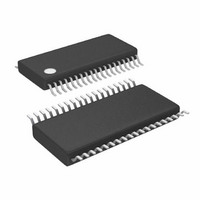
LTC3865EFE#TRPBF Linear Technology, LTC3865EFE#TRPBF Datasheet - Page 31

LTC3865EFE#TRPBF
Manufacturer Part Number
LTC3865EFE#TRPBF
Description
IC BUCK SYNC ADJ DUAL 38TSSOP
Manufacturer
Linear Technology
Type
Step-Down (Buck)r
Datasheet
1.LTC3865EUHPBF.pdf
(38 pages)
Specifications of LTC3865EFE#TRPBF
Internal Switch(s)
No
Synchronous Rectifier
Yes
Number Of Outputs
2
Voltage - Output
0.6 ~ 5 V
Frequency - Switching
250kHz ~ 770kHz
Voltage - Input
4.5 ~ 38 V
Operating Temperature
-40°C ~ 85°C
Mounting Type
Surface Mount
Package / Case
38-TSSOP Exposed Pad, 38-eTSSOP, 38-HTSSOP
Lead Free Status / RoHS Status
Lead free / RoHS Compliant
Current - Output
-
Power - Output
-
Available stocks
Company
Part Number
Manufacturer
Quantity
Price
APPLICATIONS INFORMATION
Design Example
As a design example for a 2-channel medium current
regulator, assume V
(maximum), V
f = 500kHz (see Figure 14).
The regulated output voltages are set by connecting VID11
and VID22 to INTV
The frequency is set by biasing the FREQ pin to 1.2V (see
Figure 9).
The inductance values are based on a 35% maximum
ripple current assumption (1.75A for each channel). The
highest value of ripple current occurs at the maximum
input voltage:
V
L
OUT1
3.3V
5A
=
f •
L1, L2: COILTRONICS HCP0703
M1, M2: VISHAY SILICONIX Si4816BDY
C
OUT1
Δ
V
3.3μH
C
100μF
OUT1
2
OUT
L1
5.49k
I
, C
L MAX
1%
OUT1
(
OUT2
: TAIYO YUDEN JMK325BJ107MM
1.37k
1%
CC
= 3.3V, V
)
M1
⎛
⎜
⎝
and fl oating VID12 and VID21.
IN
1
−
4.75k
1%
= 12V (nominal), V
V
1800pF
Figure 14. High Effi ciency Dual 500kHz 3.3V/1.8V Step-Down Converter
IN MAX
OUT2
V
OUT
(
0.1μF
= 1.8V, I
)
4.7μF
⎞
⎟
⎠
0.1μF
100pF
MAX1,2
D3
2.2Ω
0.1μF
IN
= 5A, and
MODE/PLLIN
I
VID11
VID12
TG1
BOOST1
SW1
BG1
SENSE1
SENSE1
V
I
V
RUN1
LIM
TH1
TK/SS1
OSENSE1
IN
= 20V
PGOOD
+
–
LTC3865
1μF
SGND
EXTV
CC
Channel 1 will require 3.2μH, and Channel 2 will require
1.9μH. The next highest standard values are 3.3μH
and 2.2μH. At the nominal input voltage (12V), the ripple
will be:
Channel 1 will have 1.45A (29%) ripple, and Channel 2 will
have 1.4A (28%) ripple. The peak inductor current will be
the maximum DC value plus one-half the ripple current,
or 5.725A for Channel 1 and 5.7A for Channel 2.
The minimum on-time occurs on Channel 1 at the maximum
V
V
SENSE2
SENSE2
BOOST2
OSENSE2
TK/SS2
IN
INTV
VID21
VID22
PGND
RUN2
FREQ
ΔI
t
, and should not be less than 90ns:
SW2
BG2
I
TG2
ON MIN
TH2
CC
L NOM
+
–
0.1μF
(
(
)
)
=
=
V
162k
1%
V
IN MAX
f
D4
OUT
LTC3865/LTC3865-1
V
0.1μF
(
•
OUT
L
0.1μF
5.49k
1%
⎛
⎜
⎝
)
2200pF
1
f
−
=
V
20 500
IN NOM
V
1.58k
1%
OUT
(
V
100pF
(
1 8
+
.
M2
)
V
⎞
⎟
⎠
kHz
22μF
50V
3.65k
1%
)
2.2μH
=
L2
180 s s
V
7V TO 20V
IN
n
3865 F14
31
C
100μF
OUT2
2
V
1.8V
5A
OUT2
3865fb


