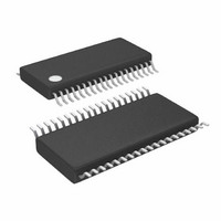
LTC3855EFE#TRPBF Linear Technology, LTC3855EFE#TRPBF Datasheet - Page 14

LTC3855EFE#TRPBF
Manufacturer Part Number
LTC3855EFE#TRPBF
Description
IC CTLR DC/DC DUAL 2PH 38TSSOP
Manufacturer
Linear Technology
Series
PolyPhase®r
Type
Step-Down (Buck)r
Datasheet
1.LTC3855EUJPBF.pdf
(44 pages)
Specifications of LTC3855EFE#TRPBF
Internal Switch(s)
No
Synchronous Rectifier
Yes
Number Of Outputs
2
Voltage - Output
0.6 ~ 3.3 V, 0.6 ~ 12.5 V
Current - Output
25A
Frequency - Switching
250kHz ~ 770kHz
Voltage - Input
4.5 ~ 38 V
Operating Temperature
-40°C ~ 85°C
Mounting Type
Surface Mount
Package / Case
38-TSSOP Exposed Pad, 38-eTSSOP, 38-HTSSOP
Lead Free Status / RoHS Status
Lead free / RoHS Compliant
Power - Output
-
Available stocks
Company
Part Number
Manufacturer
Quantity
Price
operaTion
LTC3855
Sensing the Output Voltage with a Differential
Amplifier
The LTC3855 includes a low offset, unity gain, high band-
width differential amplifier for applications that require true
remote sensing. Sensing the load across the load capaci-
tors directly greatly benefits regulation in high current, low
voltage applications, where board interconnection losses
can be a significant portion of the total error budget.
The LTC3855 differential amplifier has a typical output slew
rate of 2V/μs. The amplifier is configured for unity gain,
meaning that the difference between DIFFP and DIFFN is
translated to DIFFOUT, relative to SGND.
Care should be taken to route the DIFFP and DIFFN PCB
traces parallel to each other all the way to the terminals
of the output capacitor or remote sensing points on the
board. In addition, avoid routing these sensitive traces
near any high speed switching nodes in the circuit. Ideally,
the DIFFP and DIFFN traces should be shielded by a low
impedance ground plane to maintain signal integrity.
Inductor DCR Sensing Temperature Compensation and
the ITEMP Pins
Inductor DCR current sensing provides a lossless method
of sensing the instantaneous current. Therefore, it can
provide higher efficiency for applications of high output
currents. However the DCR of a copper inductor typically
has a positive temperature coefficient. As the temperature
of the inductor rises, its DCR value increases. The current
limit of the controller is therefore reduced.
LTC3855 offers a method to counter this inaccuracy by
allowing the user to place an NTC temperature sensing
resistor near the inductor. ITEMP pin, when left floating, is
at a voltage around 5V and DCR temperature compensa-
tion is disabled. ITEMP pin has a constant 10µA precision
current flowing out the pin. By connecting an NTC resistor
from ITEMP pin to SGND, the maximum current sense
threshold can be varied over temperature according the
following equation:
V
SENSEMAX ADJ
(
)
=
V
SENSE MAX
(
)
•
1 8
. –
1 3
V
.
ITEMP
Where:
The valid voltage range for DCR temperature compensa-
tion on the ITEMP pin is between 0.5V to 0.2V, with 0.5V
or above being no DCR temperature correction and 0.2V
the maximum correction. However, if the duty cycle of the
controller is less than 25%, the ITEMP range is extended
from 0.5V to 0V.
An NTC resistor has a negative temperature coefficient,
that means that its value decreases as temperature rises.
The V
increases and in turn the V
compensate the DCR temperature coefficient. The NTC
resistor, however, is non-linear and user can linearize its
value by building a resistor network with regular resis-
tors. Consult the NTC manufacture datasheets for detailed
information.
Another use for the ITEMP pins, in addition to NTC com-
pensated DCR sensing, is adjusting V
between the nominal values of 30mV, 50mV and 75mV for
a more precise current limit. This is done by applying a
voltage less than 0.5V to the ITEMP pin. V
be varied per the above equation and the same duty cycle
limitations will apply. The current limit can be adjusted using
this method either with a sense resistor or DCR sensing.
For more information see the NTC Compensated DCR Sens-
ing paragraph in the Applications Information section.
Frequency Selection and Phase-Locked Loop
(FREQ and MODE/PLLIN Pins)
The selection of switching frequency is a trade-off between
efficiency and component size. Low frequency opera-
tion increases efficiency by reducing MOSFET switching
losses, but requires larger inductance and/or capacitance
to maintain low output ripple voltage. The switching
V
threshold.
V
specified in the electrical characteristics table. It is typi-
cally 75mV, 50mV, or 30mV depending on the setting
I
V
LIM
SENSEMAX(ADJ)
SENSE(MAX)
ITEMP
ITEMP
pins.
is the voltage of ITEMP pin.
voltage, therefore, decreases as temperature
is the maximum current sense threshold
is the maximum adjusted current sense
SENSEMAX(ADJ)
SENSE(MAX)
will increase to
SENSE(MAX)
to values
will
3855f


