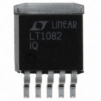
LT1082IQ#TRPBF Linear Technology, LT1082IQ#TRPBF Datasheet - Page 3

LT1082IQ#TRPBF
Manufacturer Part Number
LT1082IQ#TRPBF
Description
IC SWTCHNG REG HI-V/EFF 1A 5-DD
Manufacturer
Linear Technology
Type
Step-Down (Buck), Step-Up (Boost), Inverting, Flyback, Forward Converterr
Datasheet
1.LT1082CN8PBF.pdf
(12 pages)
Specifications of LT1082IQ#TRPBF
Internal Switch(s)
Yes
Synchronous Rectifier
No
Number Of Outputs
1
Current - Output
1A
Frequency - Switching
60kHz
Voltage - Input
3 ~ 75 V
Operating Temperature
-40°C ~ 125°C
Mounting Type
Surface Mount
Package / Case
D²Pak, TO-263 (5 leads + tab)
Power - Output
20W
Lead Free Status / RoHS Status
Lead free / RoHS Compliant
Voltage - Output
-
Available stocks
Company
Part Number
Manufacturer
Quantity
Price
I
f
BV
V
V
I
DC
temperature range, otherwise specifications are at T
specified.
SYMBOL
Note 1: Absolute Maximum Ratings are those values beyond which the
life of a device may be impaired.
Note 2: Measured with V
ELECTRICAL C
Q
LIM
FB
SAT
I
I
SW
IN
MAX
Supply Current
Control Pin Threshold
Normal/Flyback Threshold
on Feedback Pin
Switching Frequency
Output Switch Breakdown Voltage
Control Voltage to Switch
Current Transconductance
Flyback Reference Voltage
Change in Flyback Reference Voltage
Flyback Reference Voltage Line Regulation
Flyback Amplifier Transconductance (g
Flyback Amplifier Source
and Sink Current
Output Switch “On” Resistance (Note 2)
Switch Current Limit
(LT1082C)
Switch Current Limit
(LT1082I)
Switch Current Limit
(LT1082M)
Supply Current Increase
During Switch-On Time
Maximum Switch Duty Cycle
Flyback Sense Delay Time
Shutdown Mode Supply Current
Shutdown Mode
Threshold Voltage
PARAMETER
C
in hi clamp, V
HARA TERISTICS
FB
C
= 0.8V.
m
)
A
3V V
Duty Cycle = 0
CONDITIONS
800 A I
3V V
I
60 A I
I
V
I
I
Duty Cycle = 20%
Duty Cycle 50%
Duty Cycle = 80% (Note 3)
Duty Cycle = 20%
Duty Cycle 50%
Duty Cycle = 80% (Note 3)
Duty Cycle = 20%
Duty Cycle 50%
Duty Cycle = 80% (Note 3)
3V V
3V V
= 25 C. V
FB
FB
FB
SW
C
I
C
= 0.6V Source
= 60 A
= 60 A, 3V V
= 60 A Sink
= 10 A
= 0.7A (LT1082C), I
The denotes the specifications which apply over the full operating
IN
IN
IN
IN
FB
FB
V
V
V
V
IN
MAX
MAX
MAX
MAX
200 A
= 15V, V
450 A
, V
, I
, V
SW
IN
Note 3: For duty cycles (DC) between 50% and 80%, minimum
guaranteed switch current decreases linearly.
C
C
= 0.6V
= 0.05V
= 1.5mA
V
C
SW
MAX
= 0.5V, V
= 0.5A (LT1082M)
FB
= V
REF
, output pin open, unless otherwise
0.58
MIN
0.7
0.5
50
45
100
150
3.5
1.07
1.0
0.8
0.85
0.8
0.65
0.75
0.7
0.6
17
16
15
30
70
50
85
0.67
18.6
0.01
4.5
115
300
120
150
TYP
0.9
1.5
4.6
0.8
1.5
60
12
32
50
35
92
7.0
MAX
1.1
1.25
0.8
20.5
21.5
0.03
70
75
500
350
250
300
6.5
1.2
2.6
2.6
2.4
2.8
2.8
2.6
3.0
3.0
2.8
70
90
45
97
LT1082
sn1082 1082fas
UNITS
mA/A
3
%/V
mho
A/V
kHz
kHz
kHz
mV
mA
mV
%
V
V
V
V
V
V
V
A
A
A
A
A
A
A
A
A
A
A
A
s


