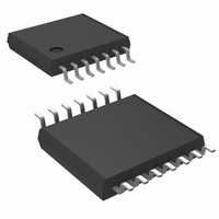
LM2743MTCX/NOPB National Semiconductor, LM2743MTCX/NOPB Datasheet

LM2743MTCX/NOPB
Specifications of LM2743MTCX/NOPB
Available stocks
Related parts for LM2743MTCX/NOPB
LM2743MTCX/NOPB Summary of contents
Page 1
... Typical Application © 2011 National Semiconductor Corporation LM2743 Features ■ Power stage input voltage from 1V to 16V ■ ...
Page 2
Connection Diagram Ordering Information Order Number LM2743MTC LM2743MTCX Pin Descriptions BOOT (Pin 1) - Bootstrap pin. This is the supply rail for the gate drivers. When the high-side MOSFET turns on, the volt- age on this pin should be at ...
Page 3
... Absolute Maximum Ratings If Military/Aerospace specified devices are required, please contact the National Semiconductor Sales Office/ Distributors for availability and specifications BOOT Voltage I SEN All other pins Junction Temperature Storage Temperature Electrical Characteristics V = 3.3V unless otherwise indicated. Typicals and limits appearing in plain type apply for T CC boldface type apply over full Operating Temperature Range ...
Page 4
Symbol Parameter GATE DRIVE I BOOT Pin Quiescent Current Q-BOOT R High-Side MOSFET Driver Pull-Up HG_UP ON resistance R High-Side MOSFET Driver Pull- HG_DN Down ON resistance R Low-Side MOSFET Driver Pull-Up LG_UP ON resistance R Low-Side MOSFET Driver Pull- ...
Page 5
Typical Performance Characteristics Efficiency (V = 1.2V) OUT V = 3.3V 300 kHz CC SW Efficiency (V = 3.3V) OUT 300 kHz CC SW BOOT Pin Current vs Temperature for BOOT Voltage = ...
Page 6
BOOT Pin Current vs Temperature for BOOT Voltage = 12V f = 300 kHz, FDS6898A FET, No-Load SW Frequency vs Temperature Switch Waveforms (HG Rising 3. 12nF, ...
Page 7
Start-Up (No-Load 3. OUT C = 12nF 300 kHz SS SW Shutdown (Full-Load 3. OUT I = 4A, ...
Page 8
Line Transient Response ( 3.3V OUT 300 kHz OUT SW www.national.com = 3V to 9V) Line Transient Response ( 1.2V 20095254 3V ...
Page 9
9 www.national.com ...
Page 10
Application Information THEORY OF OPERATION The LM2743 is a voltage-mode, high-speed synchronous buck regulator with a PWM control scheme designed for use in set-top boxes, thin clients, DSL/Cable modems, and other applications that require high efficiency buck convert- ...
Page 11
FIGURE 2. Tracking with Equal Soft-Start Time TRACKING A VOLTAGE SLEW RATE The tracking feature can alternatively be used not to make both rails reach regulation at the same time but rather to have similar rise rates (in terms of ...
Page 12
FIGURE 5. Delay for Sequencing SD PIN IMPEDANCE When connecting a resistor divider to the SD pin of the LM2743 some care has to be taken. Once the SD voltage goes above µA pull-up current is ...
Page 13
FIGURE 8. LM78L05 Feeding Basic Charge Pump Figure 9 shows a second possibility for bootstrapping the MOSFET drives using a doubler. This circuit provides an equal voltage drive and low-side MOSFET ...
Page 14
In current limit mode, by contrast, the high-side MOSFET on-pulse is skipped. This causes inductor current to fall. Unlike a normal operation switching cycle, however current limit mode switching ...
Page 15
Duty Cycle Calculation The complete duty cycle for a buck converter is defined with the following equation: where V and V are the respective ...
Page 16
OUT load transients. In this example the output current is 4A and the expected type of capacitor is an aluminum electrolytic, as with the input ca- pacitors. Other possibilities ...
Page 17
FIGURE 13. Power Stage and Error Amp One popular method for selecting the compensation compo- nents is to create Bode plots of gain and phase for the power stage and error amplifier. Combined, they make the overall bandwidth and phase ...
Page 18
The generic equation for the error amplifier transfer function is: In this equation the variable ratio of the values of the EA capacitance and resistance of the ...
Page 19
In practice, a good trade off between phase margin and band- width can be obtained by selecting the closest ±10% capac- itor values above what are suggested for C closest ±10% capacitor value below the suggestion for C and the ...
Page 20
OUT P = 0 300 kHz 61. The FDS6898A has a typical turn-on rise time t ...
Page 21
Example Circuits PART PART NUMBER U1 LM2743 Q1 FDS6898A D1 MBR0520LTI L1 DO3316P-472 C 1 16SP100M 6SP220M VJ1206Y104KXXA CC BOOT VJ0805Y332KXXA C3 C VJ0805A123KXAA SS C ...
Page 22
PART PART NUMBER U1 LM2743 Q1 FDS6898A D1 MBR0520LTI L1 DO3316P-682 C 1 16SP100M 10SP56M VJ1206Y104KXXA CC BOOT VJ0805Y182KXXA C3 C VJ0805A123KXAA SS C VJ0805A821KXAA C2 ...
Page 23
PART PART NUMBER U1 LM2743 Q1 FDS6898A D1 MBR0520LTI L1 DO3316P-332 C 1 16SP100M 6SP220M VJ1206Y104KXXA CC BOOT VJ0805Y222KXXA C3 C VJ0805A123KXAA SS C VJ0805Y332KXXA C2 ...
Page 24
Physical Dimensions www.national.com inches (millimeters) unless otherwise noted TSSOP-14 Pin Package NS Package Number MTC14 24 ...
Page 25
Notes 25 www.national.com ...
Page 26
... For more National Semiconductor product information and proven design tools, visit the following Web sites at: www.national.com Products Amplifiers www.national.com/amplifiers Audio www.national.com/audio Clock and Timing www.national.com/timing Data Converters www.national.com/adc Interface www.national.com/interface LVDS www.national.com/lvds Power Management www.national.com/power Switching Regulators www.national.com/switchers LDOs www.national.com/ldo LED Lighting www ...


